filmov
tv
Ladder Logic Documentation (Full Lecture)

Показать описание
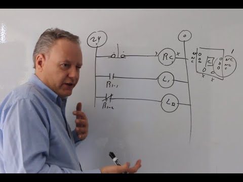
ERROR AT 23:55: NOHC FS in rung 4 should have terminal numbers 3 4, NO PS in rung 6 should have terminal numbers 3 4, NCHO FS in rung 8 should have terminal numbers 1 2
In this lesson we'll learn how to properly document a ladder logic diagram. We’ll learn to comment functional blocks, number rungs, number wires, number terminals, identify devices and associated contacts, and perform numerical cross referencing for logical elements and mechanically interlocked devices. Additionally, we’ll discuss proper grounding and circuit protection practices. (Full Lecture)
___________________
___________________
Copyright information: Use this lecture. Use it at home, at work, or at school. Put it in a playlist, embed it in a website, share it with your coworkers, family, friends, and enemies. I made this lecture and posted it on YouTube so users everywhere have free access to this information.
This being said, this YouTube channel is meant to be the sole point of distribution for this lecture. Users are not authorized to download it, change it, or charge for access. Don’t even think of downloading it and uploading to your own channel and pretending it’s your own work. Not cool. Use this lecture and let your friends know this free resource exists.
Use it. Don't steal it. Be cool.
__________________
For more FREE online technical training check out the following playlists available at the bigbadtech channel:
 0:38:46
Ladder Logic Documentation (Full Lecture)
 0:36:05
Basic Ladder Logic (Full Lecture)
 0:08:19
What is Ladder Logic?
 0:02:44
Should You Learn Ladder Logic? ABSOLUTELY NOT! PLCs are Obsolete
 0:33:09
Basic PLC Instructions (Full Lecture)
 0:06:35
PLC Ladder Logic Basics For Beginners With A Working Conveyor
 0:05:33
Introduction to Ladder Logic with Relays
 0:35:39
Basic Ladder Logic
 0:16:43
Programmable Logic Controller (PLC) : Ladder diagram
 1:55:52
Learn Beginner Level PLC Full course(ladder Logic Diagram) in just 2 hours with problems of exams
 0:56:25
PLC101 - PLC Programming Basics
 0:11:48
Relays and the Ladder Logic Diagram
 0:02:04
What is Ladder Logic? - A GalcoTV Tech Tip | Galco
 0:36:05
Basic Ladder Logic For Beginners
 0:07:03
How to Convert a Basic Wiring Diagram to a PLC Program
 0:01:42
Program Exclusive Or Using Ladder Logic (Intro To Mechatronics Part 11)
 0:01:39
What is a PLC? (90 sec)
 0:21:43
Introduction to Programmable Logic Controllers (PLCs) (Full Lecture)
 0:16:15
07-PLC Programming AND,OR,Latch program Delta PLC | Basic Ladder Diagram
 0:09:38
Electrical Circuit Basics Part 2 - Intro to Ladder Diagrams
 0:26:48
Writing Simple PLC Ladderlogic Programs
 0:09:46
Ladder Logic Best Practices: Optimizing Your PLC Programs
 0:03:53
L8 - What is counter and how to use counter in ladder logic plc programming
 0:02:55
ladder diagram | Understanding Ladder diagram | PLC logic diagram
Комментарии