filmov
tv
What Does an Orange Wire Do in an Electrical Control Panel?

Показать описание
=============================
▶ Check out the full blog post over at
=============================
Within the panel, we have a number or orange-colored wires. You may wonder what these are for, as we’ve already heard of the blue and white wires connected to the PLC.
Well, what these wires are for is to give power to devices when the main switch or panel isolator is in the OFF position.
“Why would we want to keep things on when we’ve turned the power off?” I hear you ask! “Isn’t that dangerous?” Well to put it simply, NO!
If we try to understand the different colored wires in a panel, this will help us to understand why those that are colored orange are suitable to work even when the main switch is off.
The colors of wires in panels are required by law to follow the machine safety standard EN60204-1. This is so that there is consistency and for safety.
In Power Circuits – AC and DC – we have the following color coding;
AC Phase will be BLACK
AC Neutral will be LIGHT BLUE
DC+ will be BLACK
Earth will be GREEN YELLOW
In Control Circuits – AC and DC – we have the following color coding;
AC live will be RED
AC Neutral via transformer will be RED
AC Neutral (mains) will be LIGHT BLUE
DC+ will be BLUE
Interlocks and circuits supplied from remote panels will be ORANGE – in this case, not the one we’re after!
Earth will be GREEN YELLOW
Panel services are 240VAC supplies for panel internal lighting, programming console socket outlet, internal heating & cooling, CPU's (memory backup purposes), etc.
These are 'excepted circuits' as defined in EN60204-1 and as such are not disconnected by the main panel isolator but by a separate isolator mounted inside the panel and designated 'maintained supply'.
The color coding for multicore cables;
Sheath will be ORANGE
AC live cores will be ORANGE
AC neutral cores will be ORANGE
Earth cores will be GREEN YELLOW
Color coding for single-core cables;
AC live will be ORANGE
AC neutral will be LIGHT BLUE
Earth will be GREEN YELLOW
So we come back to the original question…what wires in our panel are orange?
Well, firstly we have the panel internal light. We want to be able to see when we turn the main switch off!
Next, we have the socket. This will allow us to keep our laptop charged up. If the panel needs to be turned off for an extended period of time, then when we are ready to go, our laptop may have died. Not good! The socket is protected by a fuse so that any spikes in power won’t damage our laptop!
The final thing we have in this panel with power is a topic we’ve already covered; the thermostat and cooling fan!
As we’ve already determined, we need to be able to keep the panel cool, even when the main switch is off.
So how does this all work? Well inside the panel, we have the mains feed 3 phase power that comes into the panel to a set of terminals labeled L1, L2, L3, and N.
You can see from this that 1 phase – L1/N –has orange wires in. It is separate from the other wires in this terminal block so that they act independently.
On the back of the main switch on the left-hand door, the wires are identified as L1, L2, L3, and N, matching what we have on the terminals.
The outgoing side of this main switch will be isolated if the switch is off, and will be powered if the switch is on. The main switch is connected to the contactor labeled “150K1”.
When the switch is on, giving power to the panel, this contactor will be “pulled in” or “energized”. Once this is energized, power can be distributed around the rest of the panel.
=============================
=============================
Missed our most recent videos? Watch them here:
=============================
To stay up to date with our last videos and more lessons, make sure to subscribe to this YouTube channel:
=============================
=============================
#RealPars #PLC #ControlPanel
 0:08:01
What Does an Orange Wire Do in an Electrical Control Panel?
 0:00:26
Orange Wire?
 0:02:15
What To Do With The Orange Wire When Wiring A Aftermarket Stereo
 0:00:41
What Do Electrical Wire Colors Mean? | Mr. Electric
 0:02:09
Electrical Wire - Color Code
 0:01:40
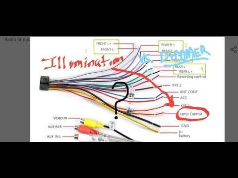
How to Wire an Illumination Wire Connection for a Car Stereo : Car Audio
 0:04:52
Understanding Wire Gauges | Ask This Old House
 0:16:14
Electrical Wire Color Coding Used By Electricians
 1:26:56
Wire BAFANG Hub + FLIPSKY 75100 Pro V2! w/ JST SM Crimp Kit
 0:00:37
What colour wire goes to L and N?
 0:00:41
Where Illumination or dimmer normally Orange wire from car head unit is connected?
 0:00:27
European Electric Cable: Blue Wire, Brown Wire & Green-Yellow Stripe (Live, Neutral, Ground)
 0:12:08
Explaining the orange wire on a CB radio (Three wires on a radio) SKIP TO 5:45 for SIMPLE ANSWER
 0:06:27
dimmer vs illumination wire/ 08 Honda Ridgeline
 0:17:15
Car Stereo Wiring Harnesses & Interfaces Explained - What Do The Wire Colors Mean?
 0:04:11
how to wire dimmer and illumination wire to a radio with out orange wire
 0:12:06
Different Types of Romex Wire or NM Electrical Cable
 0:04:32
Heat pump thermostat wire color code
 0:02:04
Beginner’s Guide How to Use Electric Wire Nuts
 0:07:07
Ethernet Cables, UTP vs STP, Straight vs Crossover, CAT 5,5e,6,7,8 Network Cables
 0:06:46
Electric Cable/Wire Colour Code || what is the color code for electric wire?
 0:10:21
Double DIN Screen Stereo Wire Colours Explained | AnthonyJ350
 0:03:08
How to properly use a wire nut.
 0:01:56
In-Sure® Push-In Wire Connectors Instructional Video
Комментарии