filmov
tv
SPI in a nutshell + Arduino & Raspberry Pi implementation: Electronics Crash Course 14
Показать описание
___
Video Article-
SPI is an ultra simple communication protocol that is cheap to implement, supports fast 10mbs transfer speeds, and is incredeibily simple to implement in your project.
SPI Stands for Serial Peripheral Interface (SPI) and is traditionally used used to send data between microcontrollers and small peripherals such as shift registers, sensors, and SD cards. It uses separate clock and data lines, along with a select line to choose the device you wish to talk to.
Like I2C, SPI uses devices called slaves and masters. Masters are typically your microcontroller such as arduino or rpi, while slaves are typically your peripherals or sensors. Note that SPI only supports one master per communication loop but SPI does support multiple slaves.
Now lets actually understand how the SPI Signal works.
Firstly we must understand that SPI uses 3-4 wires- sck, mosi, Miso, and the optional SS if you have more than one slave.
Firstly a common clock is established by the master to all the slaves via the sck wire. There are 4 modes for sampling the clock as you can see here. More details on these modes can be found in your spi devices datasheet and a more advanced tutorial on it is available in the description.
Next if you have multiple slaves, the Master will decide which slave it wants to communicate to by pulling the appropriate slave’s SS line to a low voltage.
Next the Master sends over appropriate information to the slave over the Master out slave in line (MOSI). Now there are 2 ways this information can be sent. Either with the most important bit first or the least important bit first. TO understand this lets look at the number 4037. Which digit is the most important here. Another way to think of this would be to ask which digit is most critical to the data. It is the thousands digit. SO depending on your spi device, you might need to send this bit first or last.
Now the master can also request to receive information from the slave. This is useful in situations where the slave device is a sensor of some sort. After the master is done sending its information it can send a bit requesting for a reply and the sensor will send its reply over the MISO line.
Now there are 2 ways of wiring up multiple slave devices in SPI.
Multiple slave select. This is similar to how electronics would be wired in a parallel. This method allows you to individually address each slave via a unique ss line. This method is recommended if you need individual control of slaves. However you can run out of I/O pins if you have multiple slaves since each slave needs its own SS cable
Alternatively You can daisy chain them like where the data out of each slave goes into the data in of the next slave. This is similar to how electronics are wired in series. This allows you to address all slaves with through one ss line. This method requires you to send enough data for each slave since the data overflows from one slave to the next. This method is commonly used for led clusters.
Let's discuss why one would want to use SPI especially when solutions like i2c exist
One reason that SPI is so popular is that the receiving hardware can be a simple shift register. This is a much simpler (and cheaper!) piece of hardware than the full-up UART (Universal Asynchronous Receiver / Transmitter) that asynchronous serial requires.
No start and stop bits so we can stream information continously
No need to have a slave adressing system integrated in your messages. We can simply enable a slave through a dedicated wire.
Separate data in and data out lines so 2 way simultaneous communication is possible.
Much faster than i2c
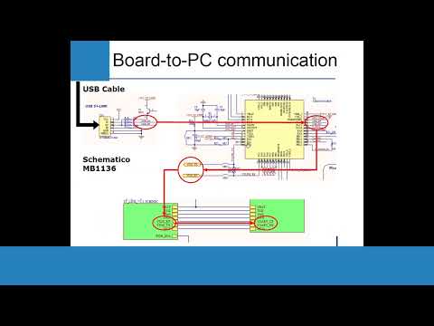
Integrating SPI into your raspberry pi or arduino project is just as simple as I2C.
Raspberry pi Implementation
These are the SPI Pins for the RPI
To activate SPI, you need to go into raspi-config, then into interfacing options and enable i2c.
Make sure to have the rpi.GPIO python package installed on your RPI
Arduino Implementation
Each arduino board has different SPI pins. The uno uses pins 10,11,12, & 13
Lastly import the SPI.h library to implement SPIin your code,
Sources
 0:06:18
SPI in a nutshell + Arduino & Raspberry Pi implementation: Electronics Crash Course 14
 0:11:13
The SPI Interface
 0:09:16
0x04 Grundlagen SPI
 0:10:03
How SPI & I2C Work - Communication Protocols | Embedded Systems Explained
 0:00:12
C++ Vs Python
 0:04:56
M11 - 5 - SPI Protocol - Operation Modes
 0:03:33
I2C and SPI: Communication Protocols – Tech Basics | Digi-Key Electronics
 0:00:13
「With Anya 's voice 🗣️she summons her Papa and Mama💀❤️🔥」Anya Spy x Family edit #anime #shorts...
 0:02:56
What is Earned Value Management? EVM in a nutshell
 0:11:16
11) Corso Programmazione Firmware STM32, protocollo di comunicazione SPI
 0:14:30
Beginners Guide to SPI on the Raspberry Pi Pico (BMP280 Example)
 0:05:56
SPI Basics
 0:01:00
What is SPI? #shorts #explained
 0:00:20
Deku's Voice CHANGED | My Hero Academia the Movie: Dark Deku ABRIDGED
 2:26:29
5)Lezione universitaria programmazione firmware. Teoria SPI andare al minuto: 1 h 34 min. ISCRIVITI
 0:00:42
Using SPI communication Protocol for interfacing ADXL345 sensor with Beaglebone Black...
 0:17:47
Tutorial: Access the SPI bus on GNU/Linux with a C programm
 0:08:19
Arduino Workshop - Chapter 5 - Using SPI
 0:02:31
How to Use Serial SPI I2C White 1.5' inch Arduino,Raspberry Pi OLED Display 128x64
 0:00:13
hUh? #history #historymemes #ww1 #austriahungary #worldwar1 #austria #hungary
 0:00:17
Talking To The Moon (Animation Meme)
 0:00:17
Spi communication
 0:09:50
How to use the SPI bus Arduino Uno vs. Arduino Mega
 0:00:20
When a Spider gets inside your Minecraft house (Animated #shorts)
Комментарии