filmov
tv
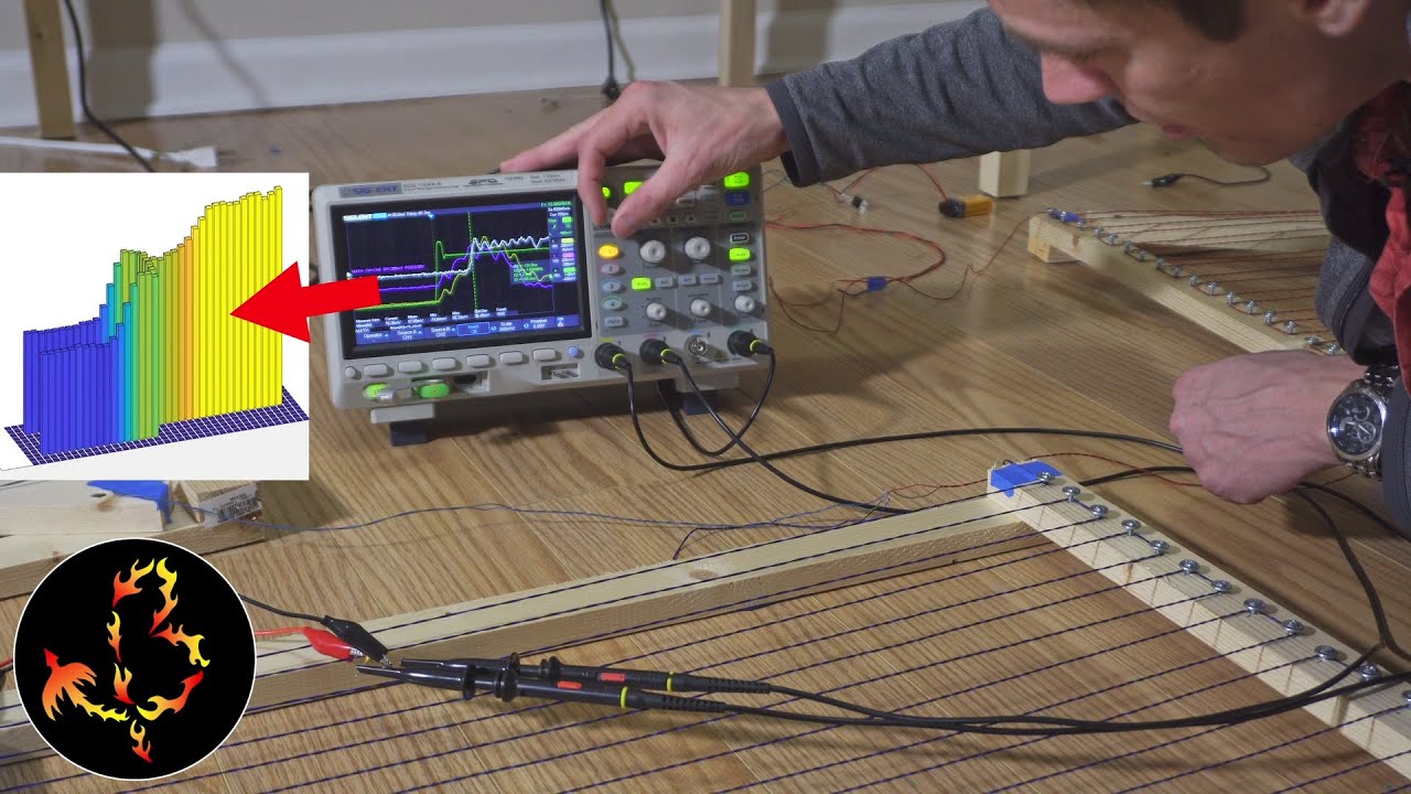
How to measure waves of electricity
Показать описание
Special thanks to my top Patreon supporters!
birdiesnbritts
John Sosa Trustham
Vladimir Shklovsky
Aloysius Sparglepartz
Ryan M
Jason Whatley
Lohann Paterno Coutinho Ferreira
Kasper Nielsen
Jeffrey Mckishen
 0:06:22
GCSE Physics - Intro to Waves - Longitudinal and Transverse Waves #61
 0:05:38
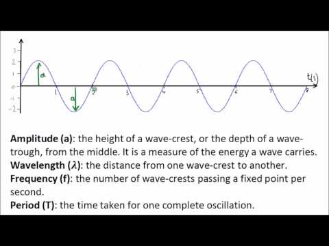
How to Measure Waves
 0:22:49
How to measure waves of electricity
 0:02:07
Measuring the Speed of Water Waves - GCSE Physics
 0:01:18
Measuring Waves
 0:12:43
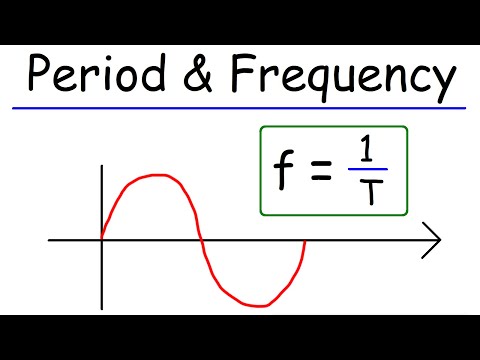
Period, Frequency, Amplitude, & Wavelength - Waves
 0:00:47
How do wave buoys measure waves around our coastline?
 0:14:28
How to Measure the Speed of Light in your kitchen! (Waves, Physics)
 0:45:27
URGENT! October 25, 2024 | Today Begins the Great Wave of 5D Ascension!
 0:00:54
Understanding Waves
 0:01:54
Measuring Big Waves
 0:03:24
Wave Equation | Waves | Physics | FuseSchool
 0:01:22
Monitoring waves and significant waves height
 0:02:18
Measuring the speed of waves on a string
 0:02:47
How to Measure Gravitational Waves | Nobel Prize Explained
 0:09:45
Measuring Waves | GCSE Science | Physics
 0:03:10
How Electromagnetic Waves Transmit Music, Messages, & More
 0:04:48
Pearson Edexcel (9-1) Combined Science and GCSE Physics – Investigating waves in solids and liquids...
 0:01:45
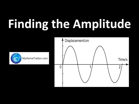
Finding the Amplitude | Waves | Physics
 0:04:36
Counting waves
 0:09:07
The Absurdity of Detecting Gravitational Waves
 0:03:34
UW|360: Measuring Ocean Waves
 0:02:36
Ripple Tank and Waves
 0:11:17
LearningTools Episode 5: How to Measure ECG Waves and Intervals
Комментарии