Budget IRS2092 500W amplifier subwoofer project powered by SMPS 500W -+58V

preview_player
Показать описание
Please read the comments before.
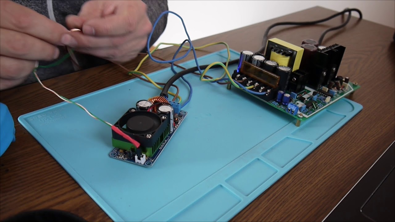
DIY IRS2092S 500W Mono Channel Digital Amplifier Class D HIFI Power Amp Board With FAN with SMPS 500W dual 58V power supply, test and results.
The Monacor subwoofer cabinet has been stripped by any filters and transformers, it is just a simple loudspeaker cabinet now.

00:00 description
00:30 SMPS power supply +-58V
01:00 500W power amplifier
01:20 about low cut filter
03:35 How to connect the SMPS and the amplifier
04:37 power up !
05:00 resistor burn out!
06:00 voltage control
06:30 let's test another board!
07:00 same resistor burned
08:00 dumping the input 22nF
08:40 more tests
10:00 440Hz test
10:45 auto oscillating problem
13:00 final remarks
Рекомендации по теме
Комментарии
Автор

I have tested these units extensively and now use them in a professional sound reinforcement application. When connected and used properly they deliver truly excellent performance. Unfortunately, this YouTube video shows very improper use. Here are some notes:

1. Choose a power supply appropriate to the speaker load. For an 8 ohm speaker, the optimum voltage is 63V. For a 4 ohm speaker use a 45V supply. The formula:
V = sqrt(500W * speaker_impedance).

2. Class D amps, such as this one, work by switching their outputs high and low at frequencies far above the audible range. What you see as "oscillation" on the output is actually the carrier frequency. Under normal conditions (connected to a speaker load) the carrier signal is about 2 Volts. Because we cannot hear above 20 kHz, and the loudspeaker cannot reproduce sound at that frequency, this carrier leakage is not a problem.

According to the manufacturer, the switching frequency should be close to 400 kHz (as it is in the modules I have purchased). The small potentiometer near the input is used to adjust that frequency. This adjustment is necessary or advisable ONLY if you have multiple modules running off of the same power supply. Improper settings greatly reduce the efficiency of the circuit and can result in overheating.

3. NEVER APPLY POWER TO THE AMP WITHOUT FIRST CONNECTING A LOAD! For testing, you can use high power resistors.
The output of the amp drives a low-pass filter. The 10 Ohm resistor is burning out because, without a proper load, the amp is delivering its high frequency carrier frequency across that filter network.

4. Toucing the input leads with your hands as you have done here, effectively couples AC line noise to the amp by using your body as an antenna. Depending on the environment, this can be several volts and can easily drive the amplifier to its full output power, potentially burning out your speaker. NEVER DO THIS! Attach the input to a proper source such as a music device or function generator.


On my bench, these amps deliver their full rated power. The signal to noise ratio (SINAD) is better than 80 dB (the limit of my test equipment), meaning that they are basically noise free. Silent, really.

The frequency response is flat over the entire audio range.

Other comments:
-- The power and speaker connectors are cheap and flimsy. You can purchase quality 0.2" spacing Phoenix connectors on the web inexpensively, and replace these.

-- The Chinese amp is based on a reference design published by the manufacturer (Infineon Technologies). For some reason, the Chinese amp uses a 100 Ohm resistor for R13 (near the input connector). The recommended value is 3.1K. I have replaced mine with 3.3K devices. This replacement is a bit tough for hobbyists, as they are surface mounted resistors.

-- Even though the amp is close to 90% efficient, at full load, it must still dissipate 50W as heat. The fan and heat sink on this unit are marginal, and the output transistors are not attached properly to the heat sink. At a minimum, be sure that you have good ventilation near the power amp. A much better choice is to replace the heat sink and fan. In my case, I desolder the output MOSFETS from the board, and attach them to a proper heat sink. I then resolder the transistors to the underside of the board, . This allows me much greater flexibility in heat sink design.

-- You may find it desirable to add some filter capacitors across the power supply input lines. Several thousand microfarads will help. Be sure to use capacitors with voltage ratings at least 20% higher than the supply voltage. Place these as close as possible to the amp to reduce the resistive losses from the power supply wires.

markcohen
Автор

Here you have a very nice forensic electronic work I may say from Engineering Essentials '' R13 modification (10 ohm to 3k) that was successful, capacitor blown up due to sustained oscillation at output. Changed capacitor. I probed every pin and point of the board. The board is very small for the purpose and the resistors are of less wattage than recommended. But it works after R13 modification, 2Hr played with high volume no problem so far. That 10Ohm resistance is just warm but the big toroid filter is getting hot during operation, even switches are very cool. Do the modification it is worth the money.'' Thanks for sharing !!

viocaia
Автор

I finally got that $15 500watt Chinese Amp operational last night. Dang!!! Its loud. The way I have it hooked up is 58VDC so it will prolly be just over 100Watts RMS. Mebby 113W. But the power supply runs Hot. roughly bout the same heat as 2 100 watt light bulbs so I need a fan on the power resistors. Calculated power draw from the plug is 1.17 Amps. Its a Power Amp chip made by Infinion. I think its an American company. So far I'm impressed. I can plug a guitar right into the input no preamp needed. But it needs a volume control. My ears are still ringing.
The PS is just a full wave bridge rectifier plugged into 117VAC wall plug, then DC is divided by 2 100watt 50 ohm resistors screwed down to a large heat sink, and filtered by 2 1000uf 100v caps.
100 watts is all Im after so I may add another 10 or 20 ohms to the resistor divider for less heat.

barneycarparts
Автор

hello,
its working good, i use dc 60v +/-, i am tested with transformer and smps everything its good, i installed use power suply transformer ac45 ct 45v (under ac45 not working) and use 2 capacitor 10000 uf 70v, dioda bridge 10A ...loud and clear

agusyuliyanto
Автор

I INSTALLED this on a powered sub as a replacement amp, I HAD SIMULAR ISSUES, it worked great after i used a lower voltage power supply 45v+/- and lower capacitance on the power supply 1500uf

selwyndookie
Автор

Hello, the board is only 250W @ 4 ohms maximum. Chinese manufacturers have difficulty understanding that two 250W channels operating in bridge are needed to provide 500W of power. This board is based on the electronic schematic of IRAUDAMP7S, but resistors R13 (100R) and R15 (130k) appear in the diagram with different values, R7 (3.01k) and R8 (120k).

Rtek-zvlr
Автор

Check the r13 of board near the audio signal side. It should be 3k. Not 100e

I bought one, which had manufacturing error. Replaced r13 with 3.3k and it worked like charm

griffinacoustics
Автор

What would explain loud clicks about every half second. Im using +-53v and 4 ohm sub. There is a preamp. Replaced the 100 ohm with 3.3k resistor. Its like it never fully turns on, heat sink cool to the touch. Has not produced sound just really loud thumps every couple of seconds.

alexanderkimani
Автор

***Tip***
That adjustment is to match two or more modules to the same operating frequency, also note with Class D Amp it's a good idea to run one amplifier with an inverted signal to cancel out Power supply bumping and, and I stress it also helps to cancel out distortion, one more thing if one channel is fed with an inverted signal that modules speaker needs to be reverse polarity.

KorAllRBare
Автор

Hi Viorel, thanks for the video. Not cientific, but nice as an information. Class D amps require special care ;-) and all of these gadgets are minimalist! Do never use the kind of SMPS or Class-D amp without additional measures like additional filtering and shielding. If you chek the IRS2092 data sheet you can see, what this unit CAN achieve! If it is used correctly and professionally. WIll keep yu informed about mine (to arrive in 2 weeks ;-)
PD.: I hope you know, voltages > 60V DC are considered lethally dangerous! (Check safety standards of your country).

michaelroek
Автор

You need to provide at least line level input audio may be from op amp pre amplifier. I have heard that i needs at least 1.5 v rms input

dushyantchaudharymathura
Автор

That is the filter for if there is no speaker, if it smokes there is a hig freqention oscilation, never use the vingers to test, because you give also rf through.

audiokees
Автор

Maybe that 10 ohm resistor is so small for the output load. Then u can try to replace it to a higher wattage as 5W

fixnreview
Автор

You should not power on the circuit without connecting the load (woofer), resistance blew off because of this. And the board did not perform well because it needs at least 1.5 watt rms from audio source so you first need to either amplify the source or use a mixer in the source.

dushyantchaudharymathura
Автор

I have bought it too, it was making smell and heat but no sound

BrightAudioSystems
Автор

Sir this amplifier needs 1.5 v RMS input so use dual power supply amp otherwise you will not be get its full power. This amp is very powerful.

vickyyadav
Автор

With Class D Amplifiers you should never EVER touch the inputs, and that's because class D amplifiers amplify way past the audio range both below and above it, ergo when you touch the input you are feeding it extremely high voltages that you body naturally has, and these voltages drive the amp beyond what it can handle.

Class D Amplifiers are switching at a extremely high frequency "beyond our hearing range" this high frequency is used to switch the output mosfets off and on at around 300Khz~600Khz, This key frequency is a square wave and to simplify this wave is a reference to switch the Output Mosfets off and on alternately, anyway long story short, that adjusting resistor sets your wave form so that the Mosfet's are switched with some dead time in between, as one works one way whilst the other after some dead time works the other way, now that oscilloscope you are using needs to measure up to at least a 1 to 2 Mhz at the very least, because you will need to adjust that resistor to the optimum frequency "usually factory set" if the module is prebuilt, change it at your own risk, if you built the amp from scratch only then will you have to adjust it for the right frequency ergo the right amount of dead time "dead time is critical if you don't want your components to blow up", also if you are setting up a stereo configuration you need to set both amplifier modules to the same optimum frequency, Check both and see which one is working at it's most optimum and then adjust the other to match it precisely, so that most if not all distortion is cancelled out especially if you invert one of the channels, once setup, they/it will drive your amplifier to it full potential, in your case a fair dinkum 500 Watts, don't forget to keep track of the phase of your signals if-n you have a stereo setup and have one with an inverted signal, also remember for that module it's speaker output is reverse phased, ergo put back into phase by treating the negative as positive and the positive as negative, if your amplifiers are not set up right you wont get the clean and powerful out put that these amplifiers are blessed with. Good Luck..

KorAllRBare
Автор

This same two board working 1 trasformer howmuch voltage and howmuch ampre need please replay

ambadi
Автор

Every time you touch those together or you touch them with your finger you're creating a dead short!
Nothing wrong with the amplifier.
You're lucky you didn't get a little burn, but if you did, maybe you would have quit shorting the amp

justinmurphy
Автор

Buen video tienes el link de compra de la fuente.?

enriqueentiquez