filmov
tv
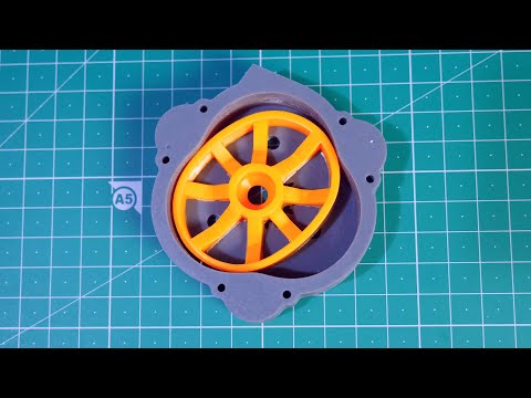
I 3D Printed a Liquid Piston Engine

Показать описание
3D Models
#rotary #engine #3dprinting
 0:12:07
I 3D Printed a Liquid Piston Engine
 0:01:00
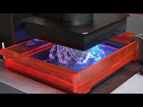
Liquid 3D printing explained
 0:14:13
I 3D Printed a LiquidPiston Engine, and it Sounds Incredible!!
 0:01:00
Rapid Liquid 3D-Printing Technology
 0:02:29
Meet the second high-resolution, laser-drawn resin 3D printer from Formlabs
 0:00:15
Heliores 3D - LIQUID PHOTOPOLYMER FOR 3D PRINTING
 0:01:40
New 3-D printer transforms liquids to solid objects in minutes
 0:02:04
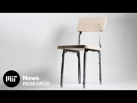
Printing furniture with liquid metal
 7:53:17
Portland XVII Alt Az Workshop, Day 2 - morning session
 0:06:34
RESIN PRINTING VS FILAMENT PRINTING | WHICH IS BETTER?
 0:19:24
How I 3D Printed a Metal Aerospike Rocket at Home
 0:01:00
3D printing technology ( continuous liquid interface production) - clip
 0:01:46
New 3-D Printer Transforms Liquids into Solid Objects in Minutes
 0:02:00
Introducing the Xerox ElemX Liquid Metal Printer | Additive Manufacturing & 3D Printing
 0:00:14
Photon Mono X2 Liquid Resin Printer from @ANYCUBIC3D
 0:00:05
😲 INCREDIBLE 3D PRINTING of liquids! 😲
 0:06:00
1. How a Resin 3D Printer Works
 0:00:26
3d printed liquid tight polypropylen canisters
 0:10:55
FAST & Smart 12K Resin 3D Printing - Anycubic Photon Mono M5s
 0:11:16
3D Printed Liquid Piston Engine - Part 1
 0:01:22
3D Printing with Liquid Aluminum | Formnext 2023
 0:09:26
How to 3D Print Liquid Simulations
 0:01:19
Liquid Metal Printing in 3-D
 0:00:26
I 3d printed a liquid metal design like #blankedstudios @BrandinoWang #3dprinting #3dprinter
Комментарии