filmov
tv
Is a Spinning Gyroscope Weightless?
Показать описание
This video is about gyroscopic motion
 0:06:44
Is a Spinning Gyroscope Weightless?
 0:03:48
Impossible Antigravity
 0:01:19
Gyroscopes in space
 0:05:42
Anti-Gravity Wheel?
 0:10:19
How Does The Anti-Gravity Wheel Work?
 0:04:16
I Finally Discovered Perpetual Motion
 0:00:20
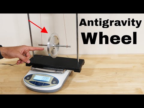
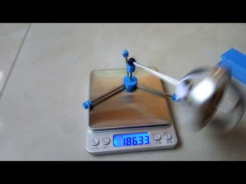
Anti-Gravity Wheel? Check the weight before and after spinning
 0:00:57
Gyro stabilization in weightlessness
 0:03:13
Why NASA Spun Astronauts Around, But Doesn't Any More
 0:00:35
Dancing T-handle in zero-g, HD
 0:00:13
Response of spinning gyroscope when pushed
 0:06:48
How Do Gyroscopes Lift Themselves Up?
 0:00:18
gyroscope effects #science #physics
 0:14:27
🔬#MESExperiments 11: Increasing Gyroscope Spin Speed Doesn't Necessarily Increase Rising Rate...
 0:01:08
Is gyroscope Anti-Gravity?
 0:00:24
Antigravity gyroscope, You deserve it
 0:04:23
Effect of Gyroscope Rotor Spin Direction on the Direction of Precession
 0:00:59
Honey in space
 0:05:41
Falling Gyroscopes and the Effect of Gravity
 0:01:04
Simple Gyroscopic Anti-gravity Debunked
 0:00:48
A physicist's favorite toy - Yula. The principle of a gyroscope #science #experiment #physics
 0:07:51
inertial propulsion with gyroscope part 18 - mass transfer-
 0:03:45
Gyroscope inside a briefcase
 0:12:11
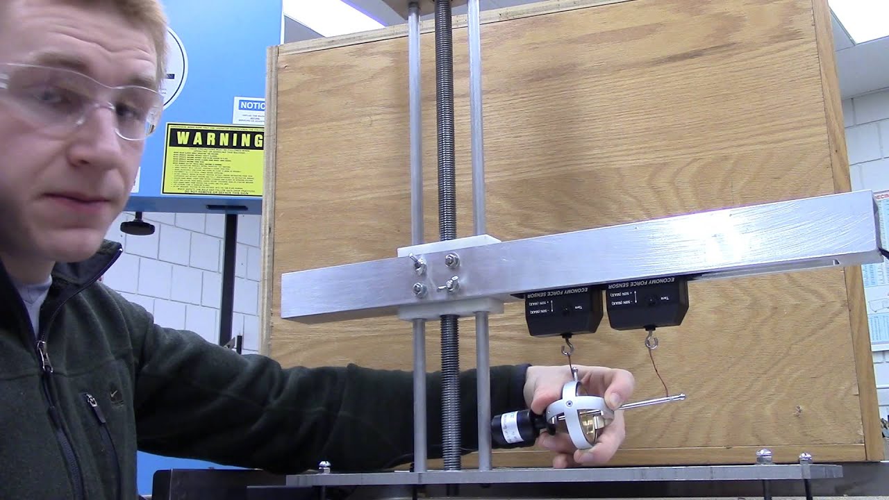
Gyroscope on a Linear Actuator on a Digital Scale and Newton's Third Law
Комментарии