filmov
tv
Arduino AC RMS Measurement

Показать описание
🔥How to emasure RMS values of AC of 220V using the ARduino and a simple module with a MCP6002 amplifier. No transformer or rectifier...
🔀LINKS
-------------------------------------
🤝SUPPORT
-------------------------------------
00:00 Intro
08:51 Thank You
Like share and subscribe to motivate me. Thank you
#electronics
#tutorial
#Arduino
 0:08:08
Arduino AC RMS Measurement
 0:09:18
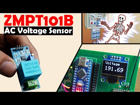
ZMPT101B 250V AC Voltage Sensor with Arduino, Voltage Monitoring
 0:03:56
Arduino AC Voltage RMS Measurement in Proteus
 0:02:06
Arduino RMS AC voltage measurement with LCD
 0:00:35
True RMS measurement using Arduino uno and LcdShield and ZMPT101B voltage sensor
 0:02:06
Arduino AC Power Meter
 0:00:26
Arduino AC Voltmeter True RMS
 0:00:16
AC 3 In 1 meter | Arduino Project
 0:24:10
#347 Measuring Mains Voltage, Current, and Power for Home Automation
 0:03:55
How To Measure AC Current With Arduino
 0:08:56
ADE7913 - AC Current Measurement and Observations
 0:19:12
Easy measure of any AC voltage with Arduino and ZMPT101B (up to 250V)
 0:03:23
Measuring RMS Value Using Arduino (Simulated Situation)
 0:11:41
AC Voltage Measurement With Arduino With Code and Circuit || Proteus Simulation
 0:25:51
RMS Voltage Sensor Part 3: Arduino Code
 0:00:21
Arduino AC current measuring ACS712
 0:21:59
RMS Voltage Measurement Using Arduino
 0:10:58
DIY ESP32 AC Power Meter (with Home Assistant/Automation Integration)
 0:08:25
How to Measure AC Current using Hall Effect Sensor with Arduino or other common Microcontrollers
 0:00:15
Measuring AC voltage using Arduino. #arduino
 0:12:15
How-to: Accurate Voltage Measurements with Arduino
 0:00:46
How measure AC voltage with arduino part 1
 0:11:22
Tutorial 16:how to measure A.C current by Arduino
 0:00:47
How to Measure Voltage with a Multimeter
Комментарии