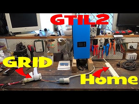
2kW Grid Tie inverter with 2 CT sensors. Part 3 of 3. For US split-phase system.

preview_player
Показать описание


As an Amazon Associate I earn from qualifying purchases.
As an Ebay Associate I earn from qualifying purchases.
Рекомендации по теме
Комментарии
Автор

Very informative and useful video. I had no problems understanding your diction even though it appears that English may not be your native language. But then, I live in the Deep South where people speak slowly with a drawl and frequently mispronounce words - so I'm used to listening carefully ! LOL

cgtotty
Автор

Excellent. You showed me that I can extend perhaps the clamp cable... several feet ...since my battery bank and the breaker panel are about 30 ft apart. Since the output is current...maybe it will have little effect at the inverter input. Therefore, I don't need to buy the extender limiter.

I read somewhere .that if you have the clamp connected at the panel ..you better have at least a resistor to dissipate the current at the end or have it already connected to the inverter. Good Job!!!

learningpower
Автор

I really appreciate this effort. And, your hard work to master the English language. I have a sincere input: Maybe find an automated translator you could feed your audio through to make it easier for North Americans to understand.
You did a great job on this and translated very useful information. Thank you.

benkanobe
Автор

Awesome! Thanks for sharing. Looking forward to seeing more of your videos. I would like to see more about your battery bank.

jimginnyohio
Автор

I would like to see like a seperate leg test for each side

dainthamos
Автор

This is good especially the limiting factor of ba k feeding to the grid.

dr.projectx
Автор

The video is very good, I just didn't quite understand the reason for installing the two sensors and which network cables they are connected to, I'm watching the video with a translator, so there is a little doubt, if you answer I'm very grateful, thank you .

renatoziva
Автор

Great video, how has this inverter held up several years later? Does it output "dirty" power that could cause issues for sensitive electronics? I'm a little concerned about the wide output range of 185V-265v

smith
Автор

Great video !!! One question. What is the maximum input current for the limiter input? Do you have a data sheet? Could it be that you destroy you input if the input current goes higher than 50mA. I think the current of both sensors is added together so there is the danger that in the worst case the input current is higher than the allowed input current.

hansdampf
Автор

I wouldn't have thought that this would work given that the two phases are out of phase with each other. But hey, it worked so well done :) :) :) I will try this on my three phase 230v.

Ulbre
Автор

very good video . thank you for sharing . do you have a video showing how you have the output from the inverter to your home grid is connected, is the AC cable connected directly to an outlet or main panel ?

adil
Автор

refers to the sensor where it should be connected

It has to be connector after the electrical box or where

BelterAltamirano
Автор

Great Information. Well Done. I am considering buying a 1.5kw system with this grid tie inverter. my meter has a round dial and looks like an older model. Pretty sure I don't need to do this hack. But great that you figured it out. Helping the common man is a great thing you have done here.

Is there a way to send the power to your battery automatically instead of it going to the grid?

JD_Manufacturing
Автор

Thank you for the video. Does the inverter calculate wattage based on voltage from the sensors? I'm just curios as to why you connected them in series and not parallel, I thought these sensors measure the current.

jasonsteeg
Автор

ok perfect what a genius are you

one question then go from the energy meter I have current 220v to 110

But then I will connect the ct to ground or negative phase or positive phase in which sir?

BelterAltamirano
Автор

At 7:50 it appears you have set up your GTI as if it were connected to Solar Panels and not battery. In this mode it will use MPPT, if you use either of the other selectable limit modes and input a setting, it is my understanding from Mars Rock that MPPT is then disabled. I need help understanding how you set up the Menu for using batteries and a what I think is a stand alone MPPT Charge Controller (Outback/Midnite). Thank you as I know I ask/asked lots of questions and you have moved way beyond these little GTIs and are using SolArk now.
The chart for my house looks similar. My base consumption is 230Watts so that is what I get from around 10PM until around 8:00AM when sun hits my panels. After 8:00AM until 6:00PM my meter reads between 0.000KW and 0.032Watts all day long. I want to have my batteries run at night and need to understand how you set up the GTIL Menu to run batteries at night and Solar during the day. Thank you!
Mine works perfect during the day and I don't need to adjust anything (I have an excellent property for solar so my ground based panels are setup for "sunrise", "mid day", and "sunset").

benkanobe
Автор

what about running each split phase leg through the one sensor, one in the opposite direction?

thedavesofourlives
Автор

Thanks for your time and effort. Great video with practical information. Do you know if this set up will work with the 1000 w version for 240vac?.

MIKE-ilmu
Автор

Great video as always. My panel is located in the exterior of my house. My set is in my garage which is 50ft away. Do you think the CT clamps will be able to ready line 1&2 because of the distance ? Thanks

andys
Автор

After 6 mnths mine has "grid error" message and no output. Company not helpful. Do you have a site or number for help? Thanks for the excellent video and for responding/helping

jeffwelch