filmov
tv
PLC (AB SLC 500) Data Masking -- Introduction to masking using an SQO sequencer block
Показать описание
The purpose of this animation is to illustrate how masking is accomplished with PLC instructions. We will start our examination of the process of masking by looking at the two input AND gate and how it operates.
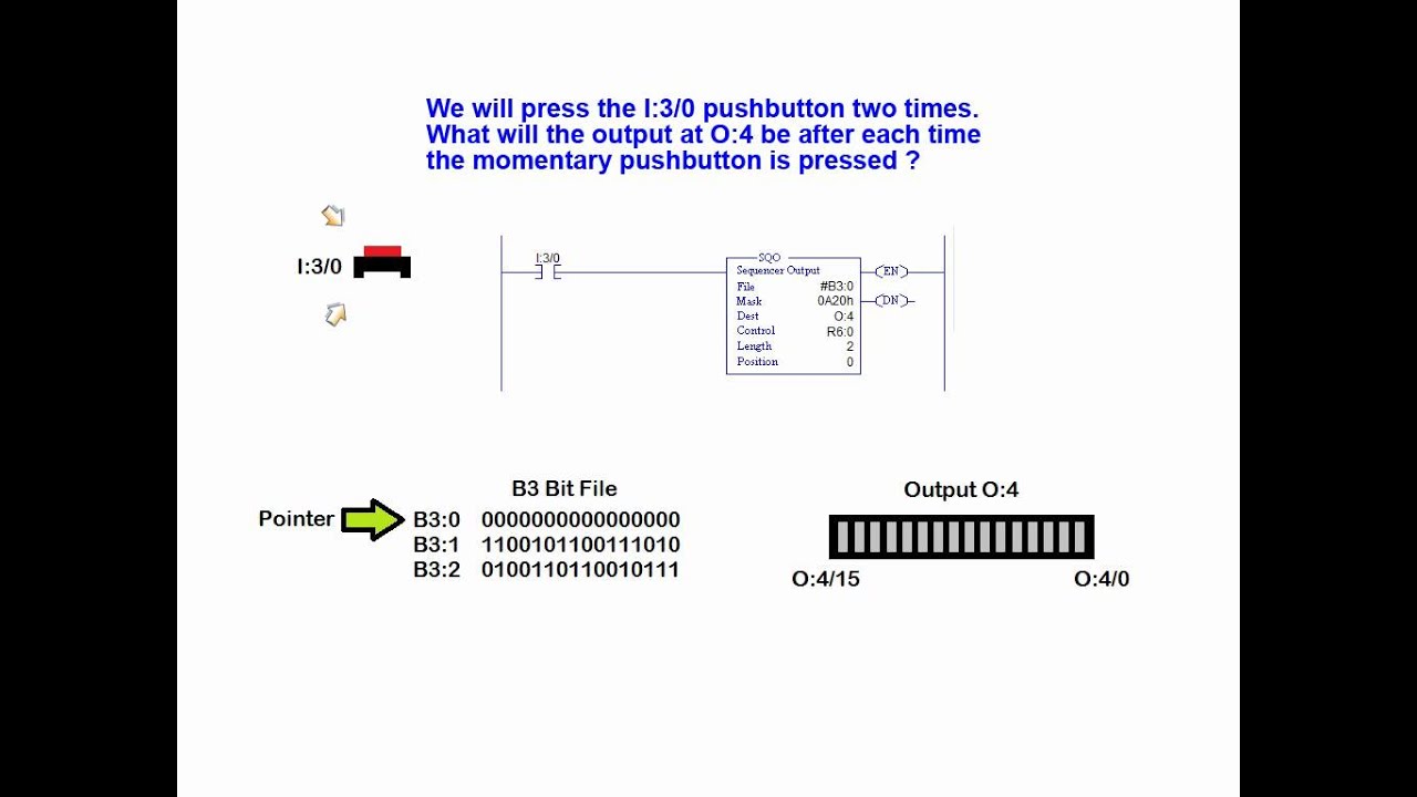
The MVM (Masked Move), the SQC (Sequencer Compare), SQO (Sequencer Output) instructions all use this masking technique to control or filter data selection. The mask value is shown in hexadecimal format as denoted by the letter h. Note that each hex digit has a 4 bit binary representation. Therefore a four digit hex mask value represents 16 binary bits.
In short, the MASK is a 16 bit hexadecimal number through which SQO instruction moves data. When MASK bit is set (i.e. binary 1) the data is passed and when MASK bit is reset (i.e. binary 0), the data is masked (blocked).
By modifying the mask value, we can selectively send parts of a data word to a desired output. This masking technique is widely used in PLC applications.
The AND gate used in this example has two inputs, A and B, and a single output Z. Along with the symbol for the AND gate, we have the Truth Table which describes the behaviour of the Z output with respect to the A and B inputs. The truth Table provides the gate output state for all possible combinations appearing at the A and B inputs. The only time at which the Z output is in the 1 state, is when inputs A and B are both in the 1 state. If either A or B is in the 0 state, the Z output will be 0. Masking uses this "AND" function to pass or block selected bits of an input or output word. Some PLC ladder logic instructions utilize this masking technique to treat data selectively.
 0:04:55
PLC (AB SLC 500) Data Masking -- Introduction to masking using an SQO sequencer block
 0:05:11
Data Transfer Using A PLC's MOV Instruction - SLC 500 Series Instruction - PLC Technician
 0:07:40
An Introduction to Allen Bradley PLCs and the Evolution of Rockwell Automation PACs
 0:04:03
RsLogix 500 Configuring PLC and Expansion Modules in I/O Configuration
 0:15:54
Sequencer SQC ,SQL ,SQO & SQI Instructions for Allen Bradley SLC 500 & MicroLogix 1500 PLCs
 0:02:17
HOW TO DOWNLOAD PROGRAM TO ALLEN BRADLEY PLC (SLC 5/01,5/02,5/03)
 0:04:09
09. Number Systems and the SLC 500 - PLC Training on Allen-Bradley Rockwell
 0:15:06
08. Memory Map, Copy and Reports on SLC 500 - PLC Training on Allen-Bradley Rockwell
 0:07:02
RsLogix 500 Uploading the Program from a Micrologix or SLC 500 PLC
 0:07:15
Message between SLC and Logix5000 (Part 1 of 2)
 0:02:00
Allen Bradley SLC 500 Cable Selection. DF1 or DH-485 ?1747-CP3 or 1747-UIC?
 0:00:39
Clearing memory from an Allen Bradley SLC 500 Including Passwords
 0:05:11
RSLogix 500 Advanced Programming Move Instructions
 0:28:36
SLC500 SEQUENCE Output explanations and test with real PLC
 0:04:53
PLC Faults in RsLogix 500 Micrologix and SLC. Is the Fault Light Flashing or Solid LED?
 0:08:39
Message (MSG) Instruction Between Two Micro Logix 1400 PLC || Allen-Bradley
 0:03:45
Rockwell AB SLC500 1747-L541 DH485 communication 1747-CP3, 1747-UIC
 0:04:39
How To Download Program On SCL 5/05 PLC CPU Lost Program On Default Factory Mode
 0:06:35
PLC Ladder Logic Basics For Beginners With A Working Conveyor
 0:17:38
Rslogix 500 Native Addressing to Studio 5000 Tag Based Addressing
 0:16:35
AB02. How to get Allen Bradley PLC data (Int, Real, String) into Excel using DDE of RSlinx Classic
 0:08:48
How to get A-B PLC data values into MS Excel using RSLinx
 2:05:49
How to Program Allen Bradley PLC Training for Beginners
 0:06:47
12. Derived Timers on SLC 500 - PLC Training on Allen-Bradley Rockwell
Комментарии