filmov
tv
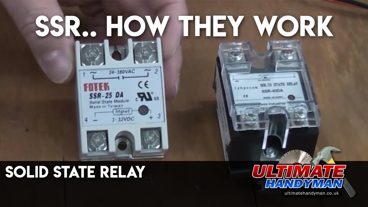
Solid state relay | SSR
Показать описание
Solid state relays are similar to traditional electromagnetic relays but they have no moving parts and the switching is done via solid state circuitry rather than an electromagnetic coil. This video demonstrates how an SSR (solid state relay) works using a bench power supply unit.
 0:02:01
Solid state relay | SSR
 0:08:17
SSR Connection With Sensor | Solid State Relay Wiring
 0:00:28
Solid State Relay, Single Phase, 200A DC-AC SSR
 0:00:12
DC load ssr relay, DC output solid state relay, DC to DC SSR relays
 0:09:19
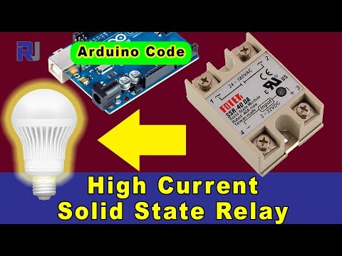
How to use Fotek SSR-40 Solid State Relay with Arduino and without Arduino
 0:10:32
How Solid State Relays Work | Testing Solid State Relay with Multimeter | Solid State Relay Wiring
 0:10:21
Solid State Relay || DIY or Buy
 0:02:36
How to test SSR Relay with a Multimeter ?
 0:00:45
'What is a Relay? Simple Explanation and Practical Uses'
 0:13:17
Teardown of an eBay 25A Solid State Relay. (SSR)
 0:03:54
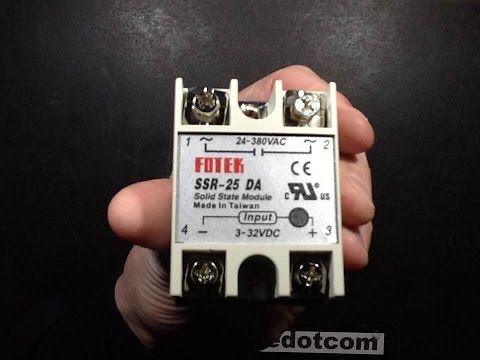
REVIEW FUTEK Solid State Relay Module SSR-25DA 25A /250V 3-32V DC Input 24-380VAC Output module
 0:00:13
how to function solid state relay (SSR)
 0:00:37
Tense Solid State Relay 3-32VDC SSR-1K1B40DA in Pakistan
 0:04:00
Spectacular solid state relay failure
 0:00:36
Solid State Relay Dual Channel Control Single Phase SSR-SK10DA in Pakistan BR4673 | Industryparts.pk
 0:02:51
What is a Solid State Relay?
 0:03:50
What is Solid State Relay | ATO SSR Overview
 0:02:55
SSR Solid State Relay - Tests Results
 0:05:45
How to wire a Solid State relay / SSR For a DC Automotive application
 0:00:36
Solid State Relay 50A/60A/80A, SSR DC-DC/AC-AC/DC-AC
 0:08:02
#293 Solid State Relay SSR JGX-1572F
 0:06:03
Motor Turn ON And OFF by using Solid State Relay | SSR Connection @TheElectricalGuy
 0:05:46
Solid State Relay (SSR) vs Electromagnetic Relay
 0:00:37
Solid State Relay SSR 25VA
Комментарии