filmov
tv
30 - RF Power Amplifier

Показать описание
Nick M0NTV completes his homebrewed 17m SSB rig with the building of an RF Power Amp. This one puts out some power!
 0:14:18
Powerblast 30 - A powerful 30 Watt 2.4Ghz RF Amplifier For QO-100 Groundstation
 0:00:31
RF Power Amplifier|1000-6000MHz Ultra-Wideband|30W|GaN|Wireless Communication|Signal Testing|Chassis
 0:06:40
70w MiniPA amplifier SSB-AM 3.5-30 MHz.How to make this amplifier and set up
 0:00:52
Class E RF amplifier 900W test
 0:23:02
30 - RF Power Amplifier
 0:00:20
BCSK-Y30 RF power amplifier module, which amplifies the 5720-5850 MHz bandwidth frequency #module
 0:00:16
My Home made RF power Amplifier 2N3904 2N2222
 0:01:56
30MHz to 512MHz, 9W GaN Wideband Power Amplifier
 0:02:06
Automatically Level RF Power Amplifier Output with Power Servo | X-Series Signal Generators
 0:02:01
30MHz to 2500MHz, 9W GaN Wideband Power Amplifier
 0:02:08
High Flatness Amplifier 10M-6GHz Gain 20/30/40DB RF Signal Driving or Receiving Front Review
 0:00:25
High Power RF Amplifier RF Power Amplifiers For Wireless Communications
 0:04:51
70MHz RF amplifier on RA30H0608M
 0:01:03
30 watts rf power booster homemade tested circuit (du1vss/radarsonic) 87-108mhz
 0:15:57
RF Power Amplifier Design
 0:10:25
EP 111 - 30dB LNA RF amplifier build and testing.
 0:06:06
RF-AMP BJ300 , ADD TO YAESU 817ND & SWR METER IN LINE (Not recommended)Test only !
 0:01:14
30w FM Transmitter - BJT Push-pull RF Power Amplifier w schematic
 0:05:13
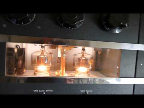
Eimac 4-400A Grounded Grid RF Amplifier Collins 30K-1 Cabinet From 1947
 0:01:22
New 2.4 GHz RF High-Power Amplifier
 0:01:55
RM Italy KL300P Will it really do 300 watts? 300 watt CB Linear Amplifier demo.
 0:00:43
Simple 30W 80 - 108 MHz RF power amplifier, circuit diagram
 0:06:47
What is Mixed Mode or Digital RF Power Amplifier?
 0:07:39
A 3.2 Watt RF Amplifier from AliExpress
Комментарии