filmov
tv
DIY Audio Spectrum Analyzer LCD Display | 6 Patterns | Arduino & 1602 LCD

Показать описание
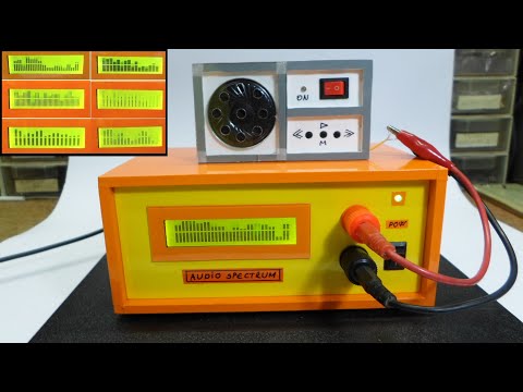
This is an Audio Spectrum Analyzer Display (LCD VU Meter) made with Arduino Nano / UNO & 16x02 LCD module. You have the option of select a pattern out of 6 and it has the power off memory (pattern stays the same even the unit power is disconnected and reconnected). Full arduino code is linked below. Enjoy!.
If you find this video enjoyable, I kindly encourage you to express your support by liking and subscribing. Your engagement not only fuels the growth of the channel but also serves as a tremendous motivation for me to create more captivating content. Thank you sincerely for your invaluable support!
Visit my other VU Meters & Audio Spectrum Analyzer Projects here
“Audio Spectrum Analyzer LCD_V1” Arduino Libraries and Arduino Code
Main Parts Links
Nano-3.0v-ATmega328-5V-16M-CH340 (Arduino Nano)
LCD16x02 Display Interactive Interface Single-Chip Blue
arduino vu meter,stereo vu meter arduino,vu meter,arduino vu meter led strip,Pixel led vu meter,arduino vu meter led,arduino pixel led vu meter,stereo vu meter,amazing light effects with vu meter using rgb led,vu meter waves,audio spectrum analyzer arduino,audio spectrum analyzer free,audio spectrum analyzer display,audio spectrum analyzer kit with display enclosure,audio spectrum analyzer,audio spectrum analyzer python,audio spectrum analyzer app,audio spectrum analyzer db rta,audio spectrum analyzer hardware,1602 lcd display,1602 lcd arduino,1602 lcd wiring,1602 lcd screen,1602 lcd 4 bit mode,1602 lcd serial interface
Track: Julius Dreisig & Mandrazo - Swalla [NCS Release]
Music provided by NoCopyrightSounds.
 0:08:50
LED Audio Spectrum Analyzer 32 Band | Arduino Nano + MAX 7219 | DIY | BejoyJustin
 0:04:48
DIY Arduino audio signal spectrum analyzer with changeable visual modes
 0:00:16
Up next open source twin audio visualizer 69 channels in stereo!
 0:04:46
DIY Audio Spectrum Analyzer LCD Display | 6 Patterns | Arduino & 1602 LCD
 0:14:24
Arduino Audio Analyzer (Tutorial for Beginners, SSD1306 OLED, u8g2, Arduino UNO)
 0:10:39
How To Make LED Music Spectrum By Using old Lcd Monitor
 0:00:24
Arduino running MSGEQ7 to a LCD for Audio Spectrum Analyzer
 0:00:16
Spectrum Analyzer LCD 16×2
 0:18:25
How to build the LCD screen music spectrum
 0:03:33
DIY Audio Spectrum display
 0:01:57
DIY Audio spectrum
 0:02:31
ARDUINO PROJECT : Audio Spectrum Analyzer LCD 2x16 + Code
 0:00:16
What I'm working on next! Coming Soon!
 0:42:51
Анализатор звукового спектра EQKIT ASD-84S - Audio Spectrum Display
 0:25:28
Audio Spectrum Display Kit assembly
 0:00:16
Amplifier Spectrum Analyzer
 0:03:45
Arduino Spectrum Analyzer using ST9720 LCD
 0:01:43
DIY Audio spectrum analyzer (LOUD)
 0:00:31
16 channel LCD spectrum analyzer with Arduino
 0:00:49
Nokia LCD with MSGEQ7 and Arduino
 0:14:49
How to make Audio Spectrum Analyzer Using KA2284 | LED VU Meter
 0:00:16
New spectrum analyzer in the making. 2 tft. And 512 external leds #pcbway
 0:01:17
DIY Arduino music spectrum analyzer with 16x2 lcd
 0:04:07
DIY LED Audio Spectrum Analyzer
Комментарии