filmov
tv
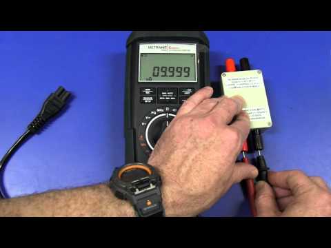
EEVblog #376 - Multimeter Fuse Diode Followup

Показать описание
How diode bridge protection across a shunt resistor in a multimeter works, and why the fuse blows before the diode does on a well designed multimeter like the Fluke.
A followup to the previous video on Multimeter input protection:
EEVblog Main Web Site:
EEVblog Amazon Store:
Donations:
Projects:
Electronics Info Wiki:
A followup to the previous video on Multimeter input protection:
EEVblog Main Web Site:
EEVblog Amazon Store:
Donations:
Projects:
Electronics Info Wiki:
 0:13:49
EEVblog #376 - Multimeter Fuse Diode Followup
 0:11:51
EEVBLOG ASTM Fuse Kit, 400mA Fuse Testing
 0:39:51
EEVblog #373 - Multimeter Input Protection Tutorial
 0:04:41
Multimeter Fuse Protection
 0:10:37
EEVblog #252 - Multimeter Ohms Overload
 0:14:32
EEVblog #374 - DIY Multimeter Calibration
 0:00:38
Even pros forget this quick and easy fix for your Fluke digital multimeter!
 0:10:38
#97 - Fluke 374 clamp meter repair
 0:02:31
Multimeter Fuse Adapter/Converter
 0:17:19
Don't Try This At Home! - Testing fuses Part 1
 0:28:00
EEVblog #715 - Mailbag
 0:01:43
6 features I love about the Fluke 117 Multimeter
 0:00:12
Good ol' fancy multimeters @twcmechanical #heavydutymechanic #heavyduty #supporttrades #bluecol...
 0:01:34
How to Replace Fuses in your Fluke Digital Multimeter Tutorial
 0:13:36
EEVblog #182 - Rode Videomic Shotgun Microphone Hack
 0:05:26
Fluke 87 Fuse Replacement
 0:04:10
How to blow a fuse and test for blown fuses on a multimeter (example basics using Fluke 87 )
 0:00:46
Saturday Projects™ .com | How to change battery and fuse in cheap multimeter. - Saturday Projects
 0:06:22
EEVBlog #263 - Extech LP100 Laser Test Probes
 0:04:13
EEVblog #177 - Baby Scale Calibration
 0:18:03
Voltlog #117 - Ebay Bussmann DMM Fuses Fake or Genuine?
 0:02:57
Fuse diodes
 0:02:02
Simple Diode Protection Circuits in Rectifiers ...
 0:15:35
Episode 94 Uni T UT71D Review Part 2
Комментарии