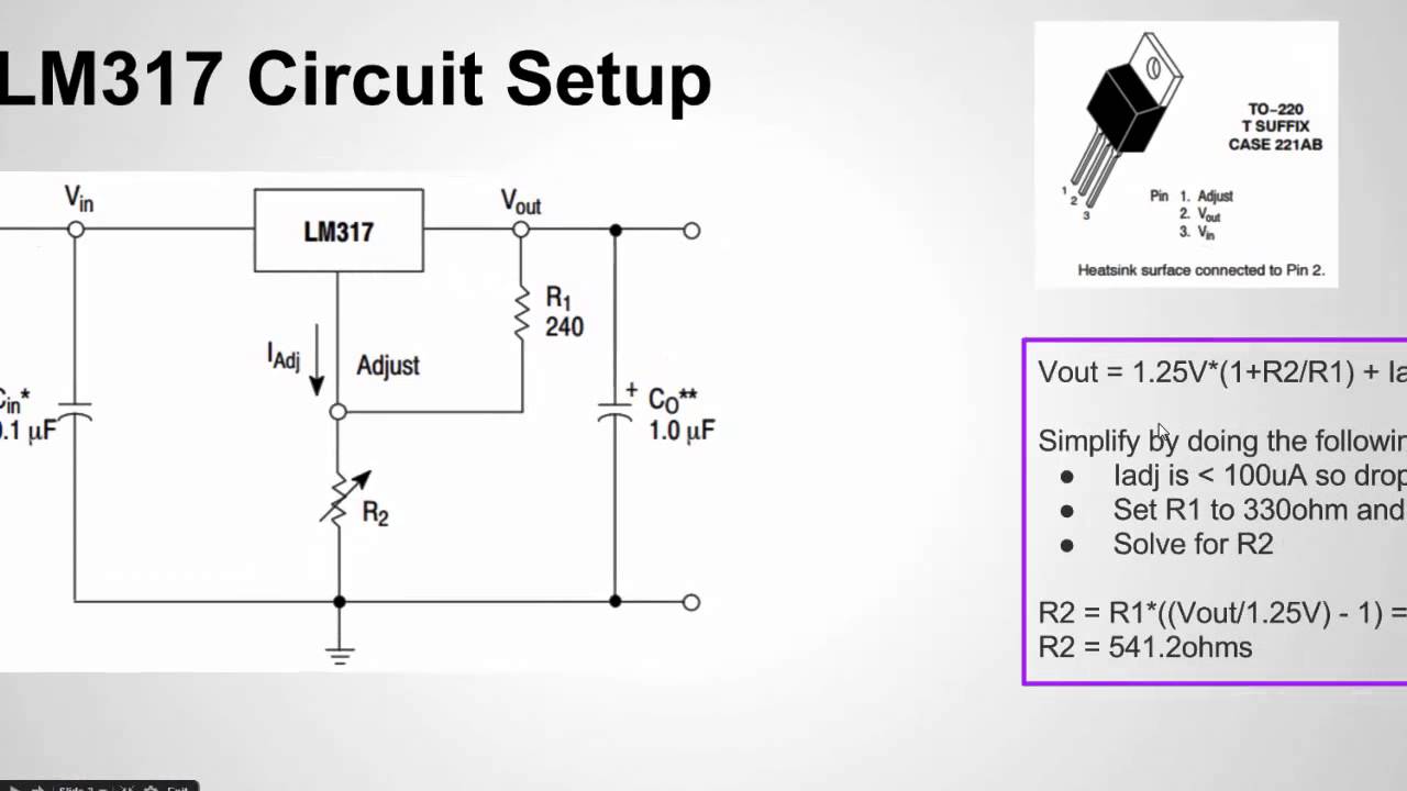
How to Configure the LM317 Voltage Regulator

preview_player
Показать описание
Рекомендации по теме
Комментарии
Автор

Thanks for this great video! I just wanted to add that these get hotter as you either draw more current or drop more voltage. Functionally, they regulate voltage by dissipating extra power as heat, EXACTLY like a series resistor would. As such, they are inefficient and are not a good choice for battery powered projects. Also, since the heat sink tab is connected to Vout, DO NOT bolt it to anything grounded (metal case or PCB pad) or you'll get a short circuit. They do shut down to try to save themselves from overheating, but don't count on this. :)

ercost
Автор

Thank you Sir😊
LM317 is a linear voltage regulator. It has the advantages of low output noise and easy configuration.

SQic_labassistant
Автор

Very Very useful video and clear explanation for the equasion.

yousifalqallaf
Автор

Thanks for this video - I needed to see how you laid it out on the breadboard to make sense of the Vin and Vout -- it's confusing when the Vin is on the left pin 3 --

ReedMunson
Автор

Your explanation is awesome, good job.

billguedesbr
Автор

Great video man, I've been looking for something like this. Most videos are just "lets put together this quick Lm317 circuit!" I like the use of the data sheet. I think it's very important if you are going in to electronics to be able to decipher data sheets. Some of the are literally like reading Chinese! (that was a 1/2 joke :] )

ameier
Автор

Good video and very helpful. Thanks much.

VeryMuchBlessed
Автор

Hi, thanks for the tutorial. One thing you want to show is how the regulator actually regulates (or not) the output voltage regardless of the load connected to it. It supposed to maintain (regulate) the voltage with or without load and any current in between. I have tested a LM317 and was disapointed with its performance, perhaps I used a damaged component.

nilobortolotti
Автор

Great video. I am however math illiterate and would love it if you could do a run through of how to do the R2 calculation. Sorry if it is basic but I've forgotten how one does sums with brackets in them.

davidturner
Автор

4.35 : the input voltage should never be much higher then the output voltage. This will cause the LM317 to generate excessive amounts of heat

TheDeathstriker
Автор

you should give the link for that data sheet and do you have a site you prefer for data sheets? search engines i use typically does n't have the old school components. i found the LT117A. works even better output voltage tolerance is a maximum of ±1%, allowing an overall power supply tolerance to be better than 3% using inexpensive 1% resistors. and same price

seamusmurphy
Автор

One thing to remember it if you want to use this to build a battery charger at 12 volts or above the variable pot will be destroyed while you are testing or using it.

felixcat
Автор

Very nice video and teacher ! does the LM317 adjusts current or voltage ? if i want to draw more than 1.5Amp, how to do ? thanks.

hichamtassi
Автор

Question- I have a heavier 24v ac transformer and a high voltage UV lamp that requires a constant AC regulated 24v 1A on its input side. Would this lm317 chip work?

mevk
Автор

what is the 100 ohm resistor on the output for? You talked about it but it is not in the circuit diagram...
Thanks

gerrys
Автор

This is the first Circuit I want to make however...I'm new to circuits and electricity in general. please somebody for the love of god explain the path of the current here that makes these resistors and reference voltage actually change the consistent output. I don't understand how a reference voltage is being created and how it's actually changing the output. For example. 12v comes in Vin to LM317. Does the path go out Vout or Adjust first or at the same time. Is it that r1 and R2 are drawing current so it comes at it both ways then once it goes through what I presume is the potentiometer in R2 it goes up the adjust terminal and out the Vout? Can current flow against itself? I'm beyond lost here.

Cawlmdownbrolololz
Автор

Sir I have query on the circuit.i had similar design I used tantalum capacitors, the problem is when the capi goes bad it is shorting the supply how to overcome this, by using same type capi

Kamal-qcqf
Автор

How high of an input voltage will it accept? I have 120v dc will that work?

jeeplvr
Автор

In equation Why you have taken 1.25V as 1.25? Does this V value always remain 1?

tushardubey
Автор

Can you give the name of any books from which I can study about

shortsbinge
join shbcf.ru