filmov
tv
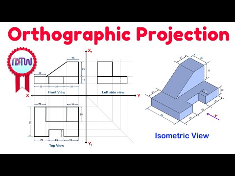
How to Draw Orthographic Views of OBLIQUE Surfaces using XYZ Coordinate System

Показать описание
Point by Point and Line by Line engineering drawing example of How to Draw Orthographic Views of an object with Oblique Surfaces that starts by defining an X Y Z Coordinate System.
Oblique Surfaces are visible faces when viewed from Front View, Top View, and Right Side View - which distinguishes them from "angled, slanted, or inclined" surfaces which still look like an edge or line from 1 direction.
Bookmark my full Engineering Graphics playlist:
TIMECODES
0:00 What is an Oblique Surface?
0:54 Engineering Drawing Coordinate System
3:05 How to draw Oblique Surfaces
4:40 Draw Front View, Top View, Right Side View
 0:09:13
Orthographic Projection from isometric view in Engineering drawing
 0:22:12
Exercise 1.1 Orthographic Drawing
 0:08:31
Orthographic projection - Engineering drawing - Technical drawing
 0:12:17
Orthographic Projection - Engineering drawing - Technical drawing
 0:06:10
Isometric View | How to Construct an Isometric View of an Object
 0:03:13
Introduction to orthographic projection
 0:02:02
Orthographic Drawing - Simplified
 0:08:09
Orthographic Projections in Engineering Drawing - Problem 4
 0:24:01
How To Convert Isometric View Into Orthographic Projection
 0:04:08
CDT G10/11 - First Angle Orthographic Projection Part 1
 0:07:02
How to draw FRONT, TOP, and RIGHT side Orthographic Views
 0:05:06
Beginning Orthographic Projection
 0:00:12
(Steps) First Angle Orthographic Projection D&T Revision Question 5
 0:09:06
ORTHOGRAPHIC TO ISOMETRIC DRAWING
 0:08:17
Mastering Orthographic Projections: Isometric View to 2D Drawing | Engineering Drawing Tutorial
 0:11:51
Orthographic Projections in Engineering Drawing - Problem 3
 0:10:15
Orthographic projection - Technical drawing - Engineering drawing
 0:21:45
ORTHOGRAPHIC DRAWING EXAMPLE
 0:13:42
ORTHOGRAPHIC PROJECTION: FIRST ANGLE PROJECTION
 0:06:13
First angles vs Third angle method | Orthographic projections animation
 0:12:49
Engineering drawing | Isometric view | Isometric drawing | How to draw isometric view
 0:07:17
Orthographic Projection in Engineering Drawing- Problem 2
 0:10:49
AutoCAD Orthographic Projection Example 1 [Multi View Drawing]
 0:09:20
Isometric View | How to Construct an Isometric View of an Object | Example: 4
Комментарии