filmov
tv
CFD in the Water Industry: Automatic Optimization of pipe system
Показать описание
This is an easy example of how automatic optimization of hydraulic structures can be achieved with CFD simulations.
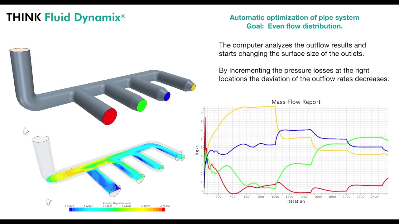
The geometry model consists on a simple pipe system with 1 inlet and four outlets (each outlet indicated with a different colour). The goal is to achieve an even flow split through the four outlets.
A CFD-solver calculates the flow distribution through the four outlets and a program evaluates the deviation and starts to change the size of the outlets ( to create additional pressure losses). For each change in the geometry the CFD-solver calculate again the flow distribution and so on. After some process-iterations the target function is fulfilled (even flow distribution) and the program stops.
The proposed example is simple and very clear. Similar procedures can be used for more complex tasks. Typical applications are the opmization of openings, baffles, etc. in hydraulic structures; the design of piping systems; the optimisation of flow distribution in complex structures and much more.
 0:03:15
 0:00:41
 0:01:05
 0:00:42
 0:06:05
 1:21:45
 1:05:11
 1:38:04
 1:16:41
 0:05:01
 0:01:10
 0:00:58
 0:00:21
 0:00:31
 0:00:40
 0:01:58
 0:01:10
 0:02:17
 0:00:21
 0:03:50
 0:05:50
 0:01:14
 0:00:09
 0:00:56