filmov
tv
LoRa Arduino Project to control Relay with feedback | Lora Tutorial 2023

Показать описание
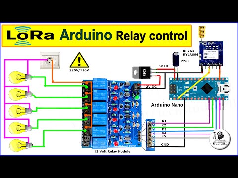
In this Arduino project, I have shown how to make the Lora project using Arduino to control relay with real-time feedback using the RYLR896 Lora module. Explained both the transmitter and receiving LoRa circuit and source codes for the Arduino UNO and how to configure the LoRa modules with AT commands.
I have covered the following topic in this Arduino Lora project:
00:33 Quick demo on the Arduino Lora project.
03:43 Explained Transmitter Lora circuit using Arduino Nano.
04:12 Explained Receiving circuit using Lora Arduino UNO
04:43 Explained source codes for Arduino Lora project
09:05 Control high voltage appliance with LoRa Module
Required components for the Transmitter Lora circuit:
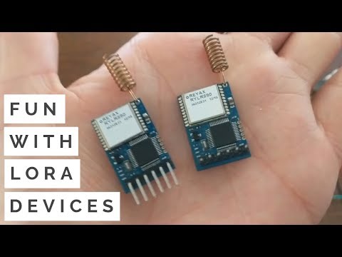
1. Lora Module REYAX RYLR896 1no
2. Arduino Nano 1no
3. 220R Resistor (1/4w) 1no
4. 4.7k Resistor (1/4w) 1no
5. 10k Resistor (1/4w) 1no
6. 5-mm LED 1no
7. 0.96" OLED Display
8. Push buttons 2no
Required components for the Receiver Lora circuit:
1. Lora Module REYAX RYLR896 1no
2. Arduino UNO 1no
3. 5v 1-channel Relay Module (Active LOW) 1no
4. 220R Resistor (1/4w) 1no
5. 4.7k Resistor (1/4w) 1no
6. 10k Resistor (1/4w) 1no
7. 5-mm LED 1no
8. Push Buttons 1no
Amazon India Affiliate links:
Amazon United States Affiliate links:
Download Code for this Arduino LoRa project
Important Links:
Important points:
1. The Network ID and BAND should be the same for the transmitter and receiving end Lora module.
2. Set the BAND as per the eligible LoRa band in your country.
3. You can use any other microcontroller for this Lora project.
4. All the AT commands for configuring the LoRa module are written in the void setup() function of the source code.
5. The range for the LoRa project will be within 5KM in rural areas. (Range will decrease if the number of obstacles increases in the signal path).
6. After the restart you have to wait till the STATUS LED turns OFF.
7. You can also connect a 30A relay to control a pump using Lora Arduino UNO.
8. If you use any other Lora module, then configure the module in setup() as per the datasheet.
9. Please watch the complete video, otherwise you may face some issues.
**Please take proper safety precautions while working with high voltages.
During this Lora tutorial video, I have explained all the required information to make this LoRa project using Arduino. You can use any other microcontrollers with the LoRa module. Both the microcontroller and LoRa module communicate through the serial terminal at the 3.3V logic level.
The range for this LoRa module is up to 5KM, So this project is very useful in rural are where WiFi is not available. The range may decrease in urban areas due to more obstacles in the path.
#lora #arduino #arduinoproject
-----------
Thanks For Watching...
✅ SUBSCRIBE ✅LIKE ✅SHARE ✅ COMMENTS
-----------
-----------
WARNING:
This video is for demonstration and educational purposes only.
Each demonstration presents risks and hazards that must be fully understood before attempting.
And should be performed only by professionals
-----------
Other useful IoT projects:
Latest ESP32 projects playlist:
Latest NodeMCU projects playlist:
Arduino Home Automation Projects playlist:
I have covered the following topic in this Arduino Lora project:
00:33 Quick demo on the Arduino Lora project.
03:43 Explained Transmitter Lora circuit using Arduino Nano.
04:12 Explained Receiving circuit using Lora Arduino UNO
04:43 Explained source codes for Arduino Lora project
09:05 Control high voltage appliance with LoRa Module
Required components for the Transmitter Lora circuit:
1. Lora Module REYAX RYLR896 1no
2. Arduino Nano 1no
3. 220R Resistor (1/4w) 1no
4. 4.7k Resistor (1/4w) 1no
5. 10k Resistor (1/4w) 1no
6. 5-mm LED 1no
7. 0.96" OLED Display
8. Push buttons 2no
Required components for the Receiver Lora circuit:
1. Lora Module REYAX RYLR896 1no
2. Arduino UNO 1no
3. 5v 1-channel Relay Module (Active LOW) 1no
4. 220R Resistor (1/4w) 1no
5. 4.7k Resistor (1/4w) 1no
6. 10k Resistor (1/4w) 1no
7. 5-mm LED 1no
8. Push Buttons 1no
Amazon India Affiliate links:
Amazon United States Affiliate links:
Download Code for this Arduino LoRa project
Important Links:
Important points:
1. The Network ID and BAND should be the same for the transmitter and receiving end Lora module.
2. Set the BAND as per the eligible LoRa band in your country.
3. You can use any other microcontroller for this Lora project.
4. All the AT commands for configuring the LoRa module are written in the void setup() function of the source code.
5. The range for the LoRa project will be within 5KM in rural areas. (Range will decrease if the number of obstacles increases in the signal path).
6. After the restart you have to wait till the STATUS LED turns OFF.
7. You can also connect a 30A relay to control a pump using Lora Arduino UNO.
8. If you use any other Lora module, then configure the module in setup() as per the datasheet.
9. Please watch the complete video, otherwise you may face some issues.
**Please take proper safety precautions while working with high voltages.
During this Lora tutorial video, I have explained all the required information to make this LoRa project using Arduino. You can use any other microcontrollers with the LoRa module. Both the microcontroller and LoRa module communicate through the serial terminal at the 3.3V logic level.
The range for this LoRa module is up to 5KM, So this project is very useful in rural are where WiFi is not available. The range may decrease in urban areas due to more obstacles in the path.
#lora #arduino #arduinoproject
-----------
Thanks For Watching...
✅ SUBSCRIBE ✅LIKE ✅SHARE ✅ COMMENTS
-----------
-----------
WARNING:
This video is for demonstration and educational purposes only.
Each demonstration presents risks and hazards that must be fully understood before attempting.
And should be performed only by professionals
-----------
Other useful IoT projects:
Latest ESP32 projects playlist:
Latest NodeMCU projects playlist:
Arduino Home Automation Projects playlist:
 0:09:47
LoRa Arduino Project to control Relay with feedback | Lora Tutorial 2023
 0:12:46
LoRa Relay Control With Arduino Upto 15KM
 1:07:58
LoRa - Long-Range Radio for IoT | Arduino, ESP32, RPI Pico
 0:13:00
How to use LoRa Module with Arduino - Range Test - RYLR406 15KM
 0:13:47
LoRa Arduino Home Automation using ESP8266 Blynk IoT | LoRa WiFi Project using RYLR998 module
 0:08:16
LoRa Project Arduino ESP8266 control Relay with feedback | Lora Tutorial using RYLR998 Lora module
 0:10:48
LoRa Arduino relay control circuit with Lora module RYLR896
 0:11:46
How to use LoRa with Arduino | LoRa Tutorial with Circuit Code and AT commands | Reyax RYLR896
 0:17:00
Which radio module? NRF24, LoRa, CC1101, HC12, 433MHz, HC05
 0:12:07
Automating a Greenhouse with LoRa! (Part 1) || Sensors (Temperature, Humidity, Soil Moisture)
 0:14:38
LoRa ESP8266 Arduino control Relay with feedback | Lora Project with Circuit using RYLR896 module
 0:11:22
Multiple LoRa Nodes Communication with Master LoRa Node using Arduino and SX1278 LoRa Module
 0:05:32
ESP32 with LoRa using Arduino IDE – Getting Started
 0:06:37
LoRa GPS Tracker Project with Google Maps - Arduino ESP8266 RYLR406
 0:11:45
LoRa SX1278/76 Arduino Interfacing Tutorial | Sending Sensor Data Wirelessly with LoRa
 0:14:39
Arduino LoRa Free SMS over Long distance without GSM Network, Arduino send SMS | LoRa Bluetooth
 0:25:03
Arduino IDE + ESP32 + LoRa Ra-02 | Communication between ESP32 using LoRa Ra-02 SX1278 433MHz
 0:10:47
Transmitting an Alarm Signal with LoRa (600m)! || Improving my Garage Alarm System
 0:14:21
LoRa Distance Testing with RYLR998 in open field - Amazing results!
 0:01:42
Arduio LoRa communication: Interfacing SX1278 (Ra-02) LoRa Module with Arduino
 0:15:51
Intro to LoRa with Arduino, Long Range Wireless for Makers (RFM95 Maduino)
 0:08:07
LoRa Module VS nRF24 VS Generic RF Module || Range & Power Test
 0:10:56
LoRa IoT Project using Arduino ESP8266 with Google Assistant and Alexa | Lora tutorial 2022
 0:06:20
Getting Started with LoRa | Tutorial
Комментарии