filmov
tv
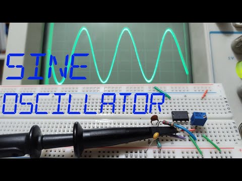
Sine Wave Generator with a 555 Timer

Показать описание
In this video, I demonstrate a sine wave generator circuit built with a 555 timer chip. I put the chip in astable mode to produce a square wave and then place an LC resonant circuit at the output to convert it to a sine wave.
 0:13:16
5 Ways To Generate A Sine Wave (Analog)
 0:22:28
QRP KITS Sine Wave Signal Generator (Kit) Part 1
 0:11:46
Does it suck? Chinese DIY Pure Sine Wave Inverter || Sinusoidal PWM (SPWM) Tutorial
 0:09:27
HONDA EU2200i Inverter Generator - Pure Sine Wave - Quiet Power
 0:07:59
Build Your Own FREQUENCY GENERATOR on a Budget (Sine, Square, & Triangle Waves)
 0:16:14
CNSWIPOWER 2000 Watt Pure Sine Wave Inverter vs Honda EU2000 Inverter Generator | Load and Waveform
 0:02:51
Portable Power Station, 110V/300W Pure Sine Wave Solar Generator
 0:08:13
What is a Sine Wave - why it is an important electronic waveform
 0:09:04
DC House RV Lithium Battery Upgrade with Renogy Pure SineWave Inverter -Affordable DIY installation
 0:17:38
60 Hz Sine Wave Generator Using 555 Timer & LC Tank Oscillator
 0:09:50
PREDATOR 2000 - Inverter Generator - Load Test - Quiet Power - Pure Sine Wave
 0:08:27
Off Grid Inverters - Pure Sine Wave vs Modified Sine Wave
 0:02:23
Digital DG-6500 watt Pure Sine Wave Inverter Generator
 0:07:25
How to convert a Modified /Square wave inverter to Pure Sine
 0:23:49
$179 at Walmart POWERSMART PS55 inverter generator (pure sine wave) 1000 rated watts & 1500 surg...
 0:03:08
Sine Wave Generator with a 555 Timer
 0:11:01
Function/Waveform Generator || DIY or Buy
 0:04:44
How to Make a Sine Wave Oscillator /w an OpAmp (Wien Oscillator)
 0:12:48
#380: Circuit Fun: Twin-Tee Oscillator - low distortion op amp sine waves
 0:17:29
Build A Simple Sine Wave Oscillator
 0:02:20
DSO-TC3 Oscilloscope Test with Signal Generator - Signal Test - Sine wave, Saw Wave
 0:00:27
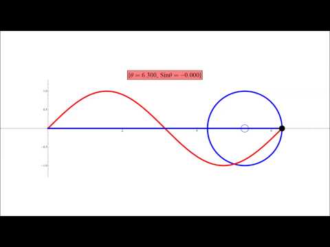
Sine Curve and the Unit Circle
 0:01:59
FG100-F4A | 1HZ-500KHZ FG-100 DDS Functional Signal Generator Sine Triangle Square Sawtooth
 0:08:58
Electrical & Electronic Waveforms: sine, square, triangular, sawtooth, ramp
Комментарии