filmov
tv
Phasor and The Phasor Diagram in AC Circuits Explained

Показать описание
In this video, phasor, and Phasor Diagram for AC circuits have been explained. And at the end, voltage and current relationship between the basic circuit elements like resistor, inductor, and capacitor has been explained using phasor diagram.
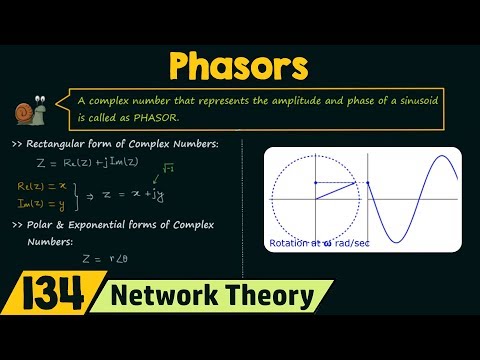
What is Phasor?
Phasor is one of the ways by which we can represent AC sinusoidal signals and we can perform arithmetic operations onto these sinusoidal signals.
Phasor is rotating the vector, which rotates around its origin at angular speed w rad/sec in anti-clockwise direction. The length of this vector represents the maximum amplitude of the sinusoidal signal and the angular velocity represents the angular frequency of the sinusoidal signal.
When phasors are represented on phasor diagram they are represented by only amplitude and phase of sinusoidal signals.
(Frequency is not represented because phasor diagram is used for signals which have same frequency but different phase and amplitude)
What is phasor diagram?
As its name suggests, phasor diagram is used to represent the phase difference between the sinusoidal signals which have the same frequency but different phase and amplitude.
Using this phasor diagram, it is easy to analyze different sinusoidal signal signals which have the same frequency.
Mathematically these phasors can be represented in three different forms.
1) Polar Form
2) Rectangular Form
3) Exponential Form
In this video, it has been shown that how to represent phasor in this three forms.
And at the end, voltage and current relationship between the basic circuit elements like resistor, inductor, and capacitor has been explained using phasor diagram.
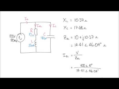
1) Resistor: For resistor, Voltage and current will be in phase
2) Inductor: For inductor, voltage will lead the current by 90 degree
3) Capacitor: For capacitor, current will lead the voltage by 90 degree
Timestamps for the different topics in the video is given below:
0:20 What is Phasor and Phasor Diagram
5:24 Mathematical representation of Phasor in different ways
6:40 Voltage and Current Relationship in Resistor using phasor diagram
7:53 Voltage and Current Relationship in Inductor using phasor diagram
10:03 Voltage and Current Relationship in capacitor using phasor diagram
11:57 Summary and simple trick to remember V-I relationship for basic circuit elements.
This video will be helpful to all students in understanding the concept of phasor and phasor diagram in the AC circuits.
Follow me on YouTube:
Follow me on Facebook:
Follow me on Instagram:
Music Credit:
What is Phasor?
Phasor is one of the ways by which we can represent AC sinusoidal signals and we can perform arithmetic operations onto these sinusoidal signals.
Phasor is rotating the vector, which rotates around its origin at angular speed w rad/sec in anti-clockwise direction. The length of this vector represents the maximum amplitude of the sinusoidal signal and the angular velocity represents the angular frequency of the sinusoidal signal.
When phasors are represented on phasor diagram they are represented by only amplitude and phase of sinusoidal signals.
(Frequency is not represented because phasor diagram is used for signals which have same frequency but different phase and amplitude)
What is phasor diagram?
As its name suggests, phasor diagram is used to represent the phase difference between the sinusoidal signals which have the same frequency but different phase and amplitude.
Using this phasor diagram, it is easy to analyze different sinusoidal signal signals which have the same frequency.
Mathematically these phasors can be represented in three different forms.
1) Polar Form
2) Rectangular Form
3) Exponential Form
In this video, it has been shown that how to represent phasor in this three forms.
And at the end, voltage and current relationship between the basic circuit elements like resistor, inductor, and capacitor has been explained using phasor diagram.
1) Resistor: For resistor, Voltage and current will be in phase
2) Inductor: For inductor, voltage will lead the current by 90 degree
3) Capacitor: For capacitor, current will lead the voltage by 90 degree
Timestamps for the different topics in the video is given below:
0:20 What is Phasor and Phasor Diagram
5:24 Mathematical representation of Phasor in different ways
6:40 Voltage and Current Relationship in Resistor using phasor diagram
7:53 Voltage and Current Relationship in Inductor using phasor diagram
10:03 Voltage and Current Relationship in capacitor using phasor diagram
11:57 Summary and simple trick to remember V-I relationship for basic circuit elements.
This video will be helpful to all students in understanding the concept of phasor and phasor diagram in the AC circuits.
Follow me on YouTube:
Follow me on Facebook:
Follow me on Instagram:
Music Credit:
 0:11:13
Phasor diagram (& its applications) | Alternating currents | Physics | Khan Academy
 0:09:48
What the HECK is a Phasor? Alternating Current Explained.
 0:13:29
Phasor and The Phasor Diagram in AC Circuits Explained
 0:13:35
Phasors
 0:05:51
Three phase electric power and phasor diagrams explained
 0:02:10
This ANIMATION shows how a ROTATING VECTOR (Phasor) creates a sin() function
 0:08:07
Phasor Diagram of Series RLC Circuit
 0:18:20
Introduction|Phasor|Diagram|Physics 12|Tamil|MurugaMP
 0:10:06
Niveles de Tensión en BAJA TENSIÓN Tendencia Europea: Sistemas 1 φ y 3 φ + Código de Colores
 0:01:00
🤫🤫what is phasor understand the AC concept #class12th #shorts
 0:09:09
Animation of Phasor Diagrams: Phase Relationships in AC Circuits
 0:04:35
How to draw a Phasor Diagram ? | Step by Step | Tech TALKS
 0:01:01
Draw the phasor diagram to represent the two sine waves shown
 1:06:03
Oscillations || SHM 03 : Phasor diagram in SHM || Circular Motion and SHM JEE MAINS/NEET ||
 0:00:15
2. Transfomer Phasor Diagram at No Load
 0:00:16
phasor diagram of transformer at no load. #electrical #transformers #lokesh @lkdhaker #lkdhaker
 0:00:57
Meaning of phasor for A.C. quantities
 0:23:06
Using Phasor Diagrams to Evaluate Series and True Parallel RLC AC Circuits
 0:00:06
phasor Diagrams..#shorts #youtube #youtubeshorts #trending #physics ...
 0:00:32
Phasor Diagrams - Voltage v/s Current Lagging/Leading Concept For R, L & C Loads #shorts
 0:11:43
AC Theory: How to Draw a Phasor Diagram for an Inductive Load to Scale
 0:17:31
Delta Phasor Diagrams
 0:08:22
Phasor Diagram of Series RL Circuit
 0:07:11
Phasor diagram - AC voltage applied to a capacitor 📝 Class 12 Physics/Chapter 7 Alternating current...
Комментарии