filmov
tv
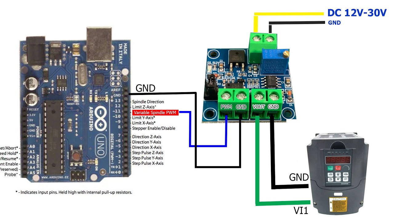
How to control VFD YL620 using Arduino with 0-10V PWM Module - ICStation -
Показать описание
WHERE TO BUY ::
PWM to Voltage Converter 0-10V PWM Module
RPM Speed control of an VFD YL620-A using Arduino GRBL with 0-10V PWM Module
Home build cnc with Arduino GRBL control cheap chinese VFD YL620 using 0-10V PWM Module
That's it for today guys, i hope you like this video thanks for watching and don't forget to Like, Comment Subscribe and Share.
Share, Support, Subscribe.!!!!!!!
→ Don't forget to subscribe!
🌟Love you all! 💕
 0:05:07
How to control VFD YL620 using Arduino with 0-10V PWM Module - ICStation -
 0:06:45
Yalang YL620/YL620-A VFD Instructions
 0:14:20
YL620-A VFD Installation Enclosure and Programming
 0:13:20
How To Program And Wire An HY VFD (Complete Breakdown)..
 0:01:49
VFD YL620-A wiring. Spindle ON/OFF , Spindle RPM control by Software (UGS)..
 0:01:14
mach3 control VFD & Spindle
 0:44:13
YL620-A Variable frequency drive installation part 1
 0:09:42
Spindle and VFD (Variable Frequency Drive) Setup Part 1
 0:13:17
Master your VFD Spindle with GRBL Control | Ultimate Tutorial | TK Designs | 4K
 0:10:19
Conexión y configuración de potenciómetro externo en VFD YL620-A
 0:36:00
CNC-Fräse China Spindel YL 620 Ein- Aus & Drehzahl mit Estlcam steuern, Anzeige in RPM | IngosTi...
 0:04:46
110V 1.5kW Spindle With VFD Setup Guide and Testing
 0:03:07
GRBLtoVFD
 0:03:23
Controlling VFD spindle rpm with XPro CNC board on ooznest OX
 0:25:11
INVERSOR YL620
 0:19:18
Setting up the Huanyang VFD for my CNC
 0:00:20
VFD YL620 A error code 4
 0:00:20
YL620 VFD controlled by linuxcnc via modbus and a rs485 usb adapter
 0:06:08
New CNC Machine EP01: Spindle Motor and YL620 Variable Frequency Drive
 0:11:02
VFD Spindle Control via OpenBuilds BlackBox Controller and Software
 0:04:51
Setting up / Testing Chinese VFD and Spindle 1.5Kw Water Cooled
 0:13:56
Conexión y configuración inicial Spindle Cuadrado 1.5kw con VFD YL620A
 0:07:35
YL620-A+BSMCE04U-PP. Подключаем, настраиваем запуск шпинделя из MACH3 и регулировку оборотов...
 0:16:10
VFD Wiring Done Correctly & Amp Usage On The Digital Interface..
Комментарии