filmov
tv
Raspberry Pi LESSON 28: Build a Programmable Temperature Sensing Alarm

Показать описание
Announcing the Most Awesome Raspberry Pi Lessons of All Times! This time we RUMBLE!
In this class series, we will be using the most excellent Sunfounder Ultimate Raspberry Pi kit, available here: (Affiliate Link)
In this video lesson I will show you my project to create a temperature sensing alarm. The device is programmable from a push button and potentiometer. An audible alarm is sounded when the temperature crosses your trip point.
If you want to grab those cool little straight jumper wires I am using to keep my breadboard builds neat and clean you can snag a box of them here:
If you guys are interested in the oscilloscope I am using, you can pick one up here (affiliate link):
You guys get your hardware ordered so you can follow along at home!
You will also need a Raspberry Pi. I suggest the Raspberry Pi 4. If you do not already have one, this is the most suitable gear I could find:
The Raspberry Pi's are sort of pricy right now, so you can look on ebay or elsewhere to see if there are any deals. You will need a SD card. If you do not already have one, this is a good one:
I like using a wireless keyboard and mouse to have fewer wires. You can certainly use your USB keyboard and mouse, but if you want a nice wireless one, this one works on the pi. We demonstrate this by using a button switch to control a LED.
You guys can help me out over at Patreon, and that will help me keep my gear updated, and help me keep this quality content coming:
#TUTORIAL
#buzzerrp
#RASPBERRYPI
 0:52:53
Raspberry Pi LESSON 28: Build a Programmable Temperature Sensing Alarm
 0:48:54
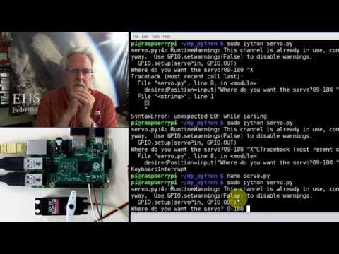
Raspberry Pi LESSON 28. Controlling a Servo with Raspberry Pi and Python
 0:14:37
Raspberry Pi Lesson 28 Homework
 0:08:15
Build A Raspberry Pi Home Theater PC that Plays Netflix, Amazon & Your Media Collection!
 0:56:00
Raspberry Pi Pico W LESSON 28: Connecting the Raspberry Pi Pico W to WiFi
 0:17:57
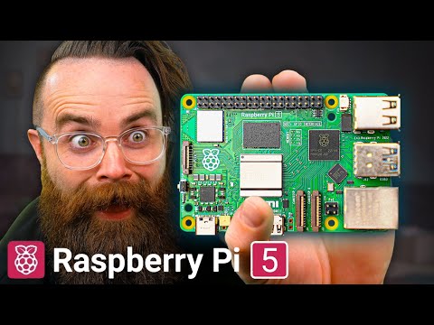
the Raspberry Pi 5
 0:27:32
Raspberry Pi Stepper Motor Tutorial
 0:18:52
Raspberry Pi RP2040 Hardware Design | Altium Designer | JLCPCB - Phil's Lab #28
 0:16:16
Raspberry Pi Pico
 0:11:03
Mini Raspberry Pi Server With Built In UPS & Stats Display
 0:12:11
How To Build a Raspberry Pi 4 NAS! (Pi 4/3/2B)
 0:11:57
Raspberry Pi Projects
 0:22:51
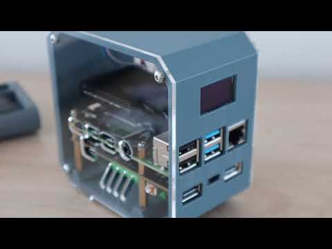
Raspberry Pi 5 Pironman 5 Case Setup with M.2 SSD: The Ultimate Build!
 0:07:54
Top 10 Raspberry Pi Projects for 2022
 0:19:21
Raspberry Pi 5 Setup: Getting Started Guide (Step By Step)
 0:20:54
Raspberry Pi demolished by monster 128-core ARM CPU!
 0:33:03
RetroPie: A Raspberry Pi Gaming Machine
 0:14:56
You call THAT a router?! 2 Tiny Raspberry Pi Routers
 0:30:22
Build a Raspberry Pi emulation system in 10 minutes!
 0:16:07
Pi 500 Maker Build: Raspberry Pi 5 Keyboard Computer
 0:10:07
#124 Cheap LoRa Gateway: Tutorial on how to Build with one with Raspberry Pi and Dragino
 0:23:53
Raspberry Pi as an Audio Streamer Guide
 0:19:11
OctoPrint: Control Your 3D Printer Remotely Using a Raspberry Pi!
 0:10:14
Setting up your Raspberry Pi Zero Starter Kit - A guide for beginners
Комментарии