filmov
tv
Understanding the Operational Amplifier

Показать описание
Even though the operational amplifier or op-amp is not a discrete component like a resistor or a capacitor, its behavior is described by a few simple rules that are as easy to understand as those of discrete parts.
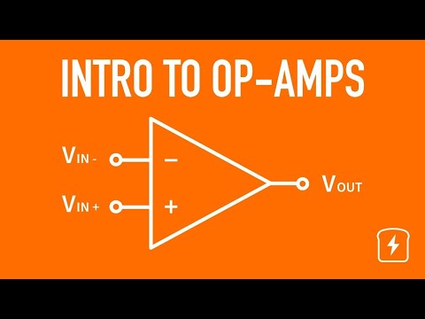
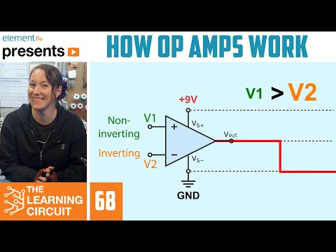
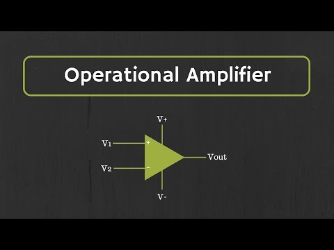
The ideal op-amp is a 3-terminal device. It has two inputs and one output. One of the inputs is non-inverting, labeled ‘+’, and the other is inverting and labeled ‘−’.
The inputs of the ideal op-amp have infinite impedance, meaning that no current can flow into them.
All the op-amp does is amplify the voltage difference present on its inputs, like this:
Vout = A • (V+ − V−)
When the op-amp is ideal, then the amplification or gain ‘A’ is infinite. In real life ‘A’ is not infinite, of course, but very large, so large that in many circuits it can be considered infinite.
Contents
--------
0:00 Intro
0:25 The operational amplifier (op-amp)
2:01 The comparator
2:59 Negative feedback
4:21 The inverting amplifier
5:44 The non-inverting amplifier
6:50 A last question
7:16 Thank you for watching
Resources
---------
* John R. Ragazzini et al., “Analysis of problems in dynamics by electronic circuits”, Proceedings of the IRE, vol. 35. p. 444, May 1947.
 0:15:09
Intro to Op-Amps (Operational Amplifiers) | Basic Circuits
 0:12:02
Operational Amplifiers - Inverting & Non Inverting Op-Amps
 0:11:34
What is an operational amplifier?
 0:11:38
Op Amp Circuits: Analog Computers from operational amplifiers
 0:06:01
Electronic Basics #21: OpAmp (Operational Amplifier)
 0:08:45
How Op Amps Work - The Learning Circuit
 0:03:03
Understanding Op Amps, Operational Amplifiers #opamp #operationalamplifier
 0:49:32
EEVblog #600 - OpAmps Tutorial - What is an Operational Amplifier?
 0:08:32
Lecture-01- Operational Amplifier: Ideal vs Practical | Understand the Real Differences
 0:13:10
Introduction to Operational Amplifier: Characteristics of Ideal Op-Amp
 0:07:32
Understanding the Operational Amplifier
 0:04:02
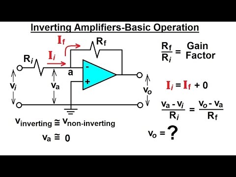
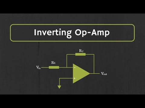
Electrical Engineering: Ch 5: Operational Amp (2 of 28) Inverting Amplifier-Basic Operation
 0:00:07
How Op Amp Integrator Works in Electronics Circuit
 0:17:14
Op-Amp (Operational Amplifier)
 0:12:20
01 - What is an Operational Amplifier? (Op-Amp Circuits)
 0:44:21
Op-Amps - Using Operational Amplifiers
 0:00:09
How Op Amp Non Inverting Amplifier Work In Electronics Circuit
 0:03:45
What is an Op Amp? - Another Teaching Moment | Digi-Key Electronics
 0:10:08
Engineer It -- Understanding operational amplifier long term
 0:00:59
What is an Op-Amp?
 0:00:48
Ideal Op Amps in a Minute #shorts
 0:17:37
Op Amp History - The Operational Amplifier - From Abstraction to Reality
 0:09:43
Operational Amplifier: Inverting Op Amp and The Concept of Virtual Ground in Op Amp
 0:00:07
Inside a Op-Amp | Internal Structure of a hybrid Operation Amplifier | Electronics Library
Комментарии