filmov
tv
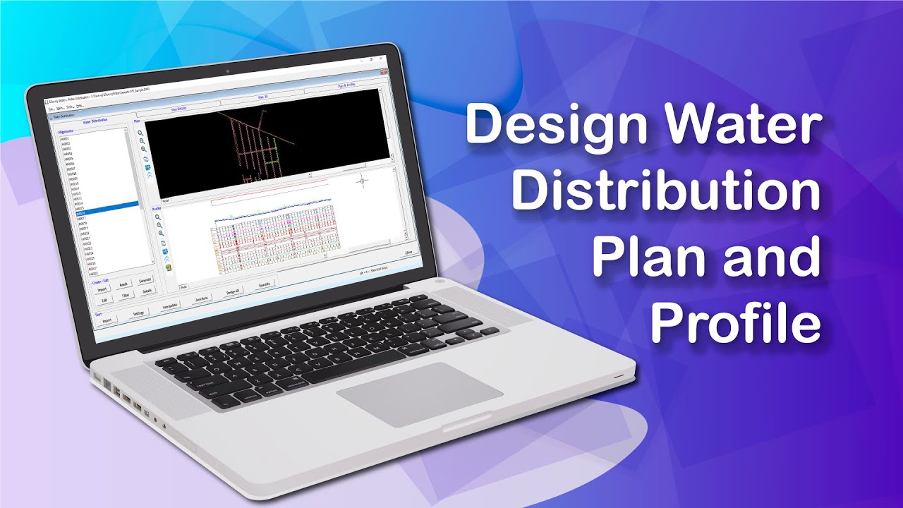
Design Water Distribution Plan and Profile
Показать описание
You can design the Formation Levels manually or the software can find out the Formation Levels depending on your preferred settings. As discussed in the earlier topics, you have to import Pipe Details, Node Details, Designed Plan Drawing, Ground Level(Elevation) and then you need to do the required Preference Settings before you design Formation Levels in Water Network. You can Design all Network lines at once.
Read more:
Hello Everyone. Welcome to the video tutorial about How to design formation levels in Water Distribution Software.
You can design the Formation Levels manually or the software can find out the Formation Levels depending on your preferred settings. As discussed in the earlier topics, you have to import Pipe Details, Node Details, Designed Plan Drawing, Ground Level(Elevation) and then you need to do the required Preference Settings before you design Formation Levels in Water Network. You can Design all Network lines at once.
To design the network lines, Click Design All button in the Water Distribution tab to design all network lines at once.
Formation design in Water distribution has 3 algorithms namely
Best Fit
Best Fit with Segmental
Best Fit with Deflection
Best Fit: This algorithm will create formation profile without considering Standard Bends and Pipe Length
Best Fit With Segmental: This Algorithm will generate Formation profile, considering Allowable deflection and it will create a segment at each pipe length
Best Fit with Deflection: This algorithm will generate Formation Profile, considering Standard bends, Pipe length and remove straight segments.
In the Design Settings, you can see that the default values are displayed based on the settings in the Master Settings dialogue for the whole project. However, you are allowed to change the properties based on the selected alignments which require modifications.
Once the changes are done, click on the Save button, and then click on the Process button to design each network line with given settings.
Please note that the column marked in yellow can be edited for each alignment if you want to change Cover Depth, Category, Process Sequence, Trench Type, and Algorithm.
After designing the Formation Level, you can see all Alignment Sections with the design details in the Profile window in the Water Distribution tab.
To view, click the Alignment Name in Water Distribution tab.
If in case you still want to modify the designed formation levels manually, for exporting the Longitudinal Section drawing to CAD, do the required modifications, use LSEXP command in CAD and export the newly designed Formation Level.
Use LSPEX command when you want to modify only the portion of formation levels of the alignment and keep the remaining formation design as it is.
Then, click on the Import Formation icon in Water Distribution Tab. The formation line will be imported.
Suppose you want to import a specific portion of the existing designed formation.
Using the LSPEX command, export only that Polyline and import in import formation.
In the Water Distribution Tab, click on the Import Formation icon. The Import Formation window opens where you need to select the Cashless Segments and then click on the Import button. A warning message will be shown saying that it will replace the existing formation at the imported portion.
Now, you can see the updated formation with the imported portion only.
Generating Quantity Reports
In the Import Alignment Tab, click on the Quantity button. The Quantity window opens where you can see the Length, Average cover depth, and the quantity for all the alignments.
By clicking on the Export button, you can export the report to an excel file as shown.
Thank you for watching this video.
In this video, you have learned how to design the formation levels.
In the next video, you will learn how to insert Turning Blocks in Plan and Profile.
Read more:
Read more:
Hello Everyone. Welcome to the video tutorial about How to design formation levels in Water Distribution Software.
You can design the Formation Levels manually or the software can find out the Formation Levels depending on your preferred settings. As discussed in the earlier topics, you have to import Pipe Details, Node Details, Designed Plan Drawing, Ground Level(Elevation) and then you need to do the required Preference Settings before you design Formation Levels in Water Network. You can Design all Network lines at once.
To design the network lines, Click Design All button in the Water Distribution tab to design all network lines at once.
Formation design in Water distribution has 3 algorithms namely
Best Fit
Best Fit with Segmental
Best Fit with Deflection
Best Fit: This algorithm will create formation profile without considering Standard Bends and Pipe Length
Best Fit With Segmental: This Algorithm will generate Formation profile, considering Allowable deflection and it will create a segment at each pipe length
Best Fit with Deflection: This algorithm will generate Formation Profile, considering Standard bends, Pipe length and remove straight segments.
In the Design Settings, you can see that the default values are displayed based on the settings in the Master Settings dialogue for the whole project. However, you are allowed to change the properties based on the selected alignments which require modifications.
Once the changes are done, click on the Save button, and then click on the Process button to design each network line with given settings.
Please note that the column marked in yellow can be edited for each alignment if you want to change Cover Depth, Category, Process Sequence, Trench Type, and Algorithm.
After designing the Formation Level, you can see all Alignment Sections with the design details in the Profile window in the Water Distribution tab.
To view, click the Alignment Name in Water Distribution tab.
If in case you still want to modify the designed formation levels manually, for exporting the Longitudinal Section drawing to CAD, do the required modifications, use LSEXP command in CAD and export the newly designed Formation Level.
Use LSPEX command when you want to modify only the portion of formation levels of the alignment and keep the remaining formation design as it is.
Then, click on the Import Formation icon in Water Distribution Tab. The formation line will be imported.
Suppose you want to import a specific portion of the existing designed formation.
Using the LSPEX command, export only that Polyline and import in import formation.
In the Water Distribution Tab, click on the Import Formation icon. The Import Formation window opens where you need to select the Cashless Segments and then click on the Import button. A warning message will be shown saying that it will replace the existing formation at the imported portion.
Now, you can see the updated formation with the imported portion only.
Generating Quantity Reports
In the Import Alignment Tab, click on the Quantity button. The Quantity window opens where you can see the Length, Average cover depth, and the quantity for all the alignments.
By clicking on the Export button, you can export the report to an excel file as shown.
Thank you for watching this video.
In this video, you have learned how to design the formation levels.
In the next video, you will learn how to insert Turning Blocks in Plan and Profile.
Read more:
 0:07:07
 0:04:13
 0:08:28
 0:20:45
 0:10:03
 0:29:02
 0:21:42
 0:28:15
 0:04:04
 0:07:56
 0:04:27
 0:06:35
 1:56:49
 0:01:47
 0:03:50
 0:44:39
 0:11:49
 0:03:25
 0:10:21
 0:10:50
 0:07:02
 0:11:00
 0:06:31
 0:00:49