filmov
tv
DIY super simple Arduino electronic component tester

Показать описание
This time I will show you how to make a super simple autodetecting and auto-ranging electronic components tester
The device is capable of testing:
- PNP, NPN transistors
- N or P Channel MOSFET
- Diodes, Double diodes
- Resistors
- Capacitors
- ESR of capacitors
- Inductors
- Thyristors, Triacs
- IGBT-transistors
The project was developed by Markus Frejek and the next Development of the project continues by Karl-Heinz Kübbeler and Markus Reshke. This is a great example of how to make a quality device with a little hardware and good software. There are many versions of this device that usually contain add-ons that complicate making and usually the software is given in the form of ready-made firmware (.hex file), which is also relatively difficult to set up on Arduino. It is also important to emphasize the use of the given libraries because they also have certain modifications
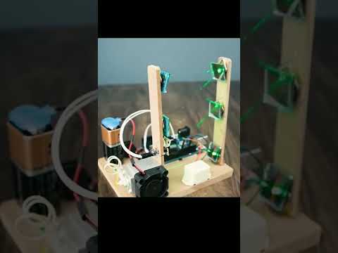
The hardware part of the device is incredibly simple and contains only a few components:
- Arduino Nano microcontroller
- Seven Resistors
- Small monochrome OLED display SSD1306
- and momentary switch
According to some instructions, the LED resistor on pin13 from Arduino should be removed (this resistor is circled in red in the picture), but in my case, the device worked without any modifications to the microcontroller. The instrument works stable with only one 3.7 Volt lithium battery.
The accuracy of the instrument mostly depends on the resistors R1 to R6, so they should have a tolerance of 1%. In addition, in the video, I will present you testing of several different electronic components.
Finally, the device is placed in a suitable box and is an indispensable accessory in your lab.
Instructions, schematics, and code at:
Visit my Youtube Channel for more Projects, DIY and How To Make videos:
by mircemk
SUBSCRIBE LIKE AND SHARE !!!!
Thanks for your Support !
Song: Jarico - Landscape (Vlog No Copyright Music)
Music promoted by Vlog No Copyright Music.
#NoCopyrightMusic #VlogMusic #VlogNoCopyrightMusic
The device is capable of testing:
- PNP, NPN transistors
- N or P Channel MOSFET
- Diodes, Double diodes
- Resistors
- Capacitors
- ESR of capacitors
- Inductors
- Thyristors, Triacs
- IGBT-transistors
The project was developed by Markus Frejek and the next Development of the project continues by Karl-Heinz Kübbeler and Markus Reshke. This is a great example of how to make a quality device with a little hardware and good software. There are many versions of this device that usually contain add-ons that complicate making and usually the software is given in the form of ready-made firmware (.hex file), which is also relatively difficult to set up on Arduino. It is also important to emphasize the use of the given libraries because they also have certain modifications
The hardware part of the device is incredibly simple and contains only a few components:
- Arduino Nano microcontroller
- Seven Resistors
- Small monochrome OLED display SSD1306
- and momentary switch
According to some instructions, the LED resistor on pin13 from Arduino should be removed (this resistor is circled in red in the picture), but in my case, the device worked without any modifications to the microcontroller. The instrument works stable with only one 3.7 Volt lithium battery.
The accuracy of the instrument mostly depends on the resistors R1 to R6, so they should have a tolerance of 1%. In addition, in the video, I will present you testing of several different electronic components.
Finally, the device is placed in a suitable box and is an indispensable accessory in your lab.
Instructions, schematics, and code at:
Visit my Youtube Channel for more Projects, DIY and How To Make videos:
by mircemk
SUBSCRIBE LIKE AND SHARE !!!!
Thanks for your Support !
Song: Jarico - Landscape (Vlog No Copyright Music)
Music promoted by Vlog No Copyright Music.
#NoCopyrightMusic #VlogMusic #VlogNoCopyrightMusic
 0:00:17
When The Quiet Kid Does Your Homework 💀 #electronics #arduino #engineering
 0:04:04
Top 10 arduino projects 2024 | Arduino projects for beginners | Arduino project
 0:06:45
DIY super simple Arduino electronic component tester
 0:00:19
DIY Radar With Ultrasonic Sensor And Chat-GPT Generated Arduino Code | Coders Cafe
 0:00:24
Arduino Make Your Uno Kit
 0:00:16
Arduino project how to make a laser electronic alarm, an amazing invention DIY
 0:00:50
8 Cool Arduino Science Projects
 0:00:40
Arduino project 😎^ Arduino #arduino #2022 #2021 #2023 #dc #arduinoproject #diy #foryou
 0:07:22
2 Simple Arduino Projects | Giveaway winner announcement!!!
 0:07:59
LED Arduino Tutorial #1 - Elegoo Uno R3 Basic Starter Kit
 0:07:04
3 Simple Arduino Projects for beginners
 0:11:28
Arduino Unboxing: Original Arduino Starter Kit vs Elegoo Uno R3 Starter Kit
 0:22:17
Get Started in Electronics #1 - Elegoo Arduino Uno Super Starter Kit
 0:19:52
SUPER SIMPLE MIDI KEYBOARD DIY HOW TO
 0:00:22
What engineering students actually do in labs 💀 #electronics #arduino #engineering
 0:07:53
Arduino Complete Starter KIT Uno R3 by Elegoo
 0:08:34
Elegoo UNO R3 Project Super Starter Kit FULL REVIEW | Arduino Robotics Kit Beginner
 0:01:00
Led Chaser Circuit Using Arduino Uno | Arduino Uno Projects | #shorts #arduino #electronics
 0:00:15
What's that?? 😲Unlocking the Power of the Arduino Multi-Function Shield: Unpacking and Overview...
 0:00:59
Arduino vs. Wires! And the winner is?
 0:00:20
Super Simple DIY Arduino 4X4 LED Matrix
 0:10:16
15 Great Arduino Projects for beginners
 0:08:29
Arduino All-in-One Robot
 0:00:20
Arduino + Mario Bros = Perfection #engineering #electronics #arduino
Комментарии