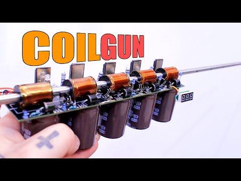
I've Made a Powerful COILGUN | Separate Stages PCB

preview_player
Показать описание

🔥Homemade gauss with separate PCB for each stage. Big coils, huge high voltage capacitors and thyristor control for powerful magnetic field. Very high speed detected with phototransistors.

🔀LINKS
-------------------------------------

🤝SUPPORT
-------------------------------------

00:00 Intro
01:41 My design & PCB
04:04 How coilgun works?
06:27 Bullet detector
08:05 Schematic
09:43 What we need
12:01 Assemble
16:21 Tests
18:26 Thank you!

Like share and subscribe to motivate me. Thank you

#project
#PCB
#homemade
Рекомендации по теме
Комментарии
Автор

Nice video, as I worked with coilguns a lot for my university project, I might give you some advice which will definitely help you.
1.try using some kind of ferrite washer caps at the both wnds of each coil, to help focusing the magnetic field.
2.the main issue and also misunderstanding about your design is that theoretically adding more stages to the design won't increase the speed.
Here is why: as the bullet passes through the stages it gains more speed, thus the required run time of each coil will be different.the early stages need more run time thus bigger inductance and capacitor values, and the few last stages will have a lot less run time due to the high speed of the bullet, so you should use smaller values of inductors and capacitors values.
If you apply the same values to each stage, adventually the last stages will reduce the speed and efficiency of the coilgun drastically, because of the suck back effect that they cause due to exceeding the required run time of the coil.
3.try to minimize the airgap between the bullet and the barrel, aslo use non-conductive barrel to get rid of induced current losses.
4. The pcb traces add a noticable amount of resistance to the current path, so using a thicker and wider trackes covered with solder is a better choice.
5.calculate the values for the capacitor and inductor of each stage based on the bullet speed of the previous stage.
6.try using a stepped coil geometry for the coil of the first stage.

These were all I can say so far about it.
Again, thanks for your efforts and keep it going!

alirezarostamifard
Автор

Great design! Make it into a loop and you have a mini particle accelerator.

SeanHodgins
Автор

What a nice project! When I was in the U.S. Navy in 1954, I was assigned to a Degaussing range on an island in Rhode Island. I learned a lot about magnetics, and sketched up a coil gun using magnetic bullets, not iron ones. I never built it but this project here brought back some great memories!

fritz
Автор

Amazing! Looks like a really fun build. I like the simplicity of being able to scale it up.

premnas
Автор

This video takes me back to when I built something similar to your design and it worked perfectly. I only used 6 stages but it was so fast when firing a small projectile through similar materials used in this video. Well done.😊

lordchristopherdeburgh
Автор

Within 17 seconds of watching this video I had to subscribe, this is litterly the type of content I enjoy. I really don't know how I haven't came across your videos earlier.

Robert-sxwe
Автор

Great video, great version of a coilgun! right now, I'm in the proces of building a Coilgun myself for a schoolproject and if there is one thing I can tell you, it is to make it a blind system, that is just controlled by an arduino or ESP. As you probably know, the magnetic field doesn't immediatly break down, when you cut the power. I used Phototransistors to get the speed and adjusted the coil timing this way.

Fabian-ldoi
Автор

The bullet detector had to be done before the coil. The resulting values would be: 1 - bullet to the coil, 0 bullet began to fly into the coil, 1 bullet flew into the coil. And after 1 -> 0 -> 1 turn on the next coil.

Noxmyn
Автор

Very nice video. Would love to see how many stages optimizes/maximizes speed.

Might also be useful as a warning of its danger if you tested it on ballistic gel at some point.

greenpeasuit
Автор

Perhaps using timing rather than photo sensors would mean more tunability. This would be more complicated because each projectile must be the same, but it could go supersonic this way :)

bertram-raven
Автор

It's good to see some new videos on this topic! I am currently designing my own multi stage modular coil gun design with optical triggers. I have designed it with fire control for single burst and auto. I can't wait to get to the prototyping stage. I almost have all my components for testing.

rhysrhysu
Автор

This is a very nice design! I like your way of making the stages modular, so you can just add more stages.
You need a way to increase the capacitor discharge rate in the last stages where the velocity is higher. All you need to do is reduce the number of turns of each stage, so as stages get less turns they have less inductance and the magnetic field will be created faster and with more intensity (but less duration).

Also, if you connect ALL the led sensors to a scope channel, you will see a series of pulses as the projectile triggers each sensor. That should allow you to calculate the acceleration for each stage, and help you to tune each stage by the number of turns on the coils.

How many turns did you use in this prototype? Did you measure the inductance?

wizrom
Автор

i love both coil and rail guns in the diy space. both have their own drawbacks and pros but in the end are very fun to play with.

blendpinexus
Автор

Nice. I've always wanted to make one where you can just attach more segments to the end ever since I knew how they worked but didn't have the sanity for a project like that. Looks great!

owenkegg
Автор

I very much like the modularity :-) ... BUT your actual circuit works a bit different, than explained in the video: the IR-barrier is positioned in front of the coil. As soon as the projectile interrupts the IR-barrier, the thyristor is switched on and the capacitor is discharged via the coil with a very high current. At that time the projectile is attracted by the magnetic field, and pulled into the coil. When the projectile exits the coil, there is no active switching off, because a thyristor can't be actively switched off. However the discharge time won't take long - the capacitor is most likely empty, before the projectile exits the coil. But there is another issue with the circuit: the discharge current reaches its peak, when the voltage of the capacitor zero. Then the current starts decreasing and charges the capacitor in reverse (the bypass-diode D2 is useless). As soon as the current is zero, the thyristor is inactive again, and the capacitor is negatively charged. Reverse-charging an electrolytic capacitor is not a good idea: I strongly recommend to test the discharge-behavior with the oscilloscope (at a much lower voltage), fix the circuit, use a high voltage mosfet (instead of the thyristor).

ChristophLaimer
Автор

Very neat project! A tip on the soldering though as some of them look very poor. I recommend soldering with a medium thick chisel tip and with some more heat for much easier work and much better flow around the joints. it might sound odd that using a bigger tip would be better and might look harder with small parts but you can turn the tip so you get the sharper edge towards the surface which makes you easily apply solder on the flat surface of it and nicely flow on to the component. if you solder with leaded solder around 380 degree C or if lead free up to 400-420 if you have bigger heat absorbing areas (might sound hot for some but this is where I work all the time). a needle tip is weak in every aspect both in how much heat it can transfer and the amount of solder it can hold and it is more suited for smaller SMD work. But I am using chisel tip for pretty much everything. just mention this as creative feedback, keep up the good work!

Pulverrostmannen
Автор

Woaw, it is indeed powerful.
Impresive how it can pass through the prefab board!
And the design is very modular and simple, I love the idea.
Just wanna see more videos on this project :)

sgrouge
Автор

This is the coolest tutorial for a coil gun that I've seen yet. Very educational and well done!

kennethcason
Автор

You should have placed the photo sensors at the front of the coil, instead of the back. Then set them to turn on the coils when the beam is blocked. The reason is that you would not need to have the coil on all the time and there will also be no pull back after the projectile has already reached past the half-way mark in the coil and starts to get a pull back effect. The coil would turn on when the projectile gets to the front of the opening and the coil will shut off when it reaches the mid-way point before any pull back happens.

Tom-ycjv
Автор

After studying his schematics, it appears that when the projectile breaks the IR beam it triggers the Thyristor of the next coil in the chain (note: the next coil circuit is drawn to the left of the IR trigger components - schematics should have a left to right flow when possible), but it DOES NOT cut off the coil that fed that IR pair. Once a coil's Thyristor is triggered, each coil is rapidly energized and then rapidly de-energized until the capacitor is nearly fully drained (note: the diode above the capacitor is an isolation diode so each capacitor discharge is independent from each other - that is good), but each coil in succession is not turned off as he says in this video, they are just drained to zero at their own rate after triggered and thus that reduces the acceleration efficiency of the system. The idea is to have the field at zero as it transitions roughy midway between one stage to the next. Timing here is very critical, if the coil de-energizes even a microsecond too early or too late, the net acceleration between stages is lower than optimum - optimum is what you need. Also I said 'roughly' between stages because that midway point might actually be somewhere within the feeding coil before passing to the accepting coil in the next stage. So exactly when and how fast one coil's magnetic field reacts (Gauss curve), it must properly overlap with the next stage's coil Gauss curve and timing. Each stage will have different timing and curves. Also, as you can see in the video, IR phototransistors have very slow response times, too slow for the pinpoint timing required for efficient acceleration. I think Hall Effect transducers would be better, but the coil fields would interfere with them and the projectile would have to be magnetized. This system is a simple rail gun, Rail Guns use pre-calculated ballistic expectations of the projectile and the system for the best results - no real-time monitoring of the projectile is used. A high speed FPGA with nanosecond timing using DLLs could get the right timing for each coil stage once a solution for the interstage ballistics is found.

paulromsky
visit shbcf.ru