filmov
tv
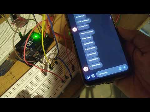
Arduino Power Loss Detection with 2 Components - Saving State to EEPROM

Показать описание
Short(ish) overview on a very simple way to detect wether your Arduino project is loosing power.
Usually when such an event is detected, you'd want to save variables you wish to survive reboots to EEPROM (be it internal or external)
Usually when such an event is detected, you'd want to save variables you wish to survive reboots to EEPROM (be it internal or external)
 0:12:00
Arduino Power Loss Detection with 2 Components - Saving State to EEPROM
 0:23:03
How to Detect Loss of Power on an Arduino for Backing Up to EEPROM
 0:02:57
Electronics: Detect Arduino power failure and save data (2 Solutions!!)
 0:00:31
Arduino remember it last state even losses power
 0:01:29
Saving Arduino state when power is lost
 0:26:08
#114 No contact mains detector for Arduino & Pi 🥧(just 10 components)
 0:00:10
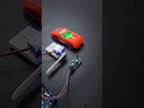
Beyond the Basics: Automatic Gatekeeper With IR Sensor And ChatGPT Generated Arduino Code
 0:00:17
When The Quiet Kid Does Your Homework 💀 #electronics #arduino #engineering
 0:00:22
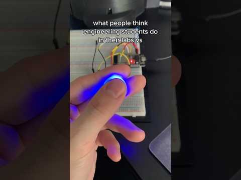
What engineering students actually do in labs 💀 #electronics #arduino #engineering
 0:09:16
Latch Circuit - Wake up + 0 Power Consumption (useful circuit)
 0:00:08
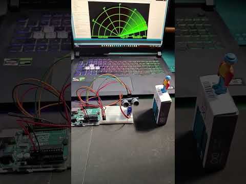
How To Make Radar With Arduino || Arduino Project.
 0:16:14
simulation of power failure detector circuit using arduino in proteus
 0:00:16
Arduino project how to make a laser electronic alarm, an amazing invention DIY
 0:00:13
Arduino based automatic water tap usingultra sonic sensor and micro servo
 0:13:54
{699} Mains Failure Detector Using Arduino
 0:00:16
✌🏻How Smart Dustbin Work Using Ultrasonic sensor Arduino & servo motor🔭Science Exhibition projec...
 0:00:59
Why Resistors are Designed to Fail Well #shorts #electronics #arduino #foryou #fyp #interesting
 0:09:46
Reducing Arduino’s Power Consumption Part 4 (Turning Off the BOD)
 0:04:17
3 phase power failure alert system Arduino and gsm sim800l
 0:00:13
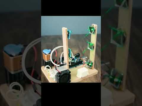
How to make water tank overflow alarm | contactless water sensor | arduino project #diy #experiment
 0:00:21
#robot #humanoid #Arduino My humanoid robot inmoov working on voice commands
 0:01:01
Server switch on after power failure using Arduino Part 1
 0:24:14
Low Power Arduino! Deep Sleep Tutorial
 0:06:54
how to make automatic three phase faults detection using arduino
Комментарии