filmov
tv
Op-Amp (Operational Amplifier) Practice Problems

Показать описание
Josh stated in the op-amp intro tutorial that operational amplifiers (op-amps) are really quite easy because of the two golden rules of op-amps but didn't give any examples of how to use those rules. In this tutorial, Josh goes through three practical operational amplifier practice problems to show how to utilize those rules to simplify circuit analysis with op-amps.
Parts of the video:
0:00 Introduction
0:30 Review of the 2 Golden Rules
0:55 First Practice Problem
4:45 Second Practice Problem
7:33 Third Practice Problem
10:27 Summary
11:54 The toast will never pop up
CircuitBread is joining the fight to help people more easily learn about and use electronics. With an ever-growing array of equations, tools, and tutorials, we're striving for the best ways to make electronics and electrical engineering topics more accessible to everyone. Come learn electronics with us!
Connect with CircuitBread:
 0:12:17
Op-Amp (Operational Amplifier) Practice Problems
 0:22:09
02 - Non-Inverting Op-Amp (Amplifier) Problems, Part 1
 0:06:57
Easiest way to solve Op-amp questions/ Op-amp nodal analysis.
 0:12:02
Operational Amplifiers - Inverting & Non Inverting Op-Amps
 0:07:27
Circuits 1 - Ideal Op-amp Example
 0:07:31
Op Amps Tutorial : Circuit Analysis
 0:21:54
Operational Amplifiers Practice Problem
 0:17:34
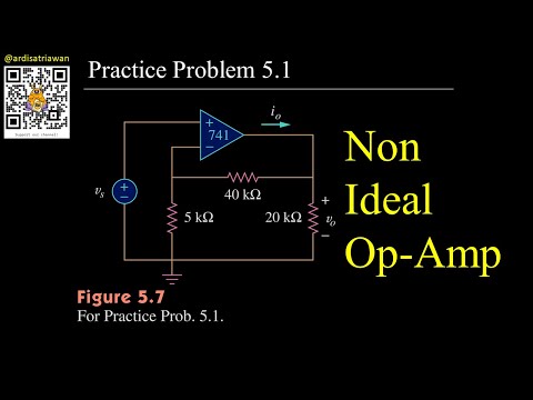
Practice Problem 5.1 Fundamental of Electric Circuits (Sadiku) 5th Ed Op-amp (Operational Amplifier)
 0:49:32
EEVblog #600 - OpAmps Tutorial - What is an Operational Amplifier?
 0:08:24
Practice Problem 5.1 Fundamental of Electric Circuits (Sadiku) 5th Ed Op-amp (Operational Amplifier)
 0:07:37
Ideal OpAmp Example Problem
 0:15:09
Intro to Op-Amps (Operational Amplifiers) | Basic Circuits
 0:12:35
Op-Amps - Applications (Sample Problems) #3
 0:06:56
Operational Amplifier Solved Problem | Quiz # 433
 0:05:52
Summing Amplifiers - Op Amp Circuits
 0:13:58
How to solve Numerical problems of Op amp
 0:01:39
Difference Amplifier using the Op-Amp Solved Problem | FAQ # 2
 0:08:39
Operational Amplifier Solved Problem | Quiz # 446
 0:02:40
Ideal Op Amp Circuit Analysis
 0:05:04
Easiest way to solve Op-amp questions
 0:14:04
Circuits 1 - Operational Amplifiers
 0:03:12
#39 OPAMP problems 1 | inverting & non inverting Amplifier || EC Academy
 0:44:21
Op-Amps - Using Operational Amplifiers
 0:18:30
Nodal Analsys of Op-Amp Circuits
Комментарии