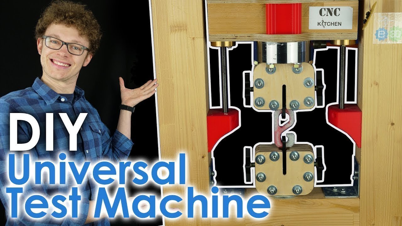
Fully OPEN SOURCE Universal Test Machine!

preview_player
Показать описание
This is my DIY Universal Test Machine that I use in many of my videos to test the strength of different materials and parts. I finally gathered all the data and made it available open source so that everyone can build on on their own. I'll go through the whole setup and also show how I managed to build an optical extensometer to measure the strain in the test samples.

💚 Support me 💚
Join as a YouTube member!

🎙Check out my PODCAST with Tom Sanladerer

⚙ My gear (Affiliate Links):
🎥 CAMERAS & LENSES
🎙AUDIO
🔴 LIVE STREAMING

Some parts you'll need:

🏆 Do you want to help me cover my running costs? Send me a dollar or two over PayPal, it helps me a lot!
🌼 Even watching the ads before my videos helps me a lot!

Disclaimer: This video was sponsored by Skillshare.
Рекомендации по теме
Комментарии
Автор

Hi Stefan. Releasing this was a big gamble for you and I think it is a really altruistic thing to do.
I hope that like the early releases of 3D printer designs, you have now started a revolution in home-testing, and you become a legend for doing so. You have done something amazing for the Community. I hope you feel really proud of yourself. You should.

SusiBiker
Автор

I use to work in an analytical testing facility for plastics and I thought I'd let you know a few tricks I found when doing these tests.


1. Grab the standard for testing plastics, ISO or ASTM. For tensile testing in the US I used ASTM D638. There is a lot of good information in them that can help you perform your tests in a repeatable way. One of the most important parts of tensile testing is the cross head speed, plastics are shear sensitive, and thus can behave differently at different speeds. The goal is to have the lowest speed that causes rupture within 30 seconds to 5 minutes.
2. The design of most grippers use a self help design. The jaws are closed by a wedge moving down which pushes the jaws together. Any tension on the system causes the jaws to grip tighter. This allows the sample to stay centered during the entire test.
3. For extensometers We had multiple different types, additionally, some tests didn't even use the extensometer; just the cross head position. For small deflections, and whenever you need to determine the modulus an extensometer must be used. For stiff materials, we used a small extensometer which could only measure up to 0.5" of deflection, but was very accurate. The other one we used was a high deflection extensometer which could measure up to the full length of the cross head movement. They are actually very simple devices they are just small strain gages with high deflection and a wheatstone bridge. The large displacement ones are just rotary encoders attached to a string to measure the displacement.
4. The machine we used was extremely simple, it ran old DOS software so it's completely feasible to build something similar.
5. To capture the break point you are looking for a certain percentage spike in either motor torque, transducer force, or extensometer position.


I could go one, but those were just some things I could think of. Good work on building this machine!

capnthepeafarmer
Автор

As a fellow mechanical engineer in Additive Manufacturing I can't wait to learn more about materials with this project. Thank you very much for sharing.

TotallyGlitch
Автор

This is very cool and interesting video. As a mechanical engineering student I always find your videos very interesting. Thank you for shearing with us your knowledge.

sasha_beliu
Автор

This is some of your best work. Very well done.

AirsoftTeamOSMD
Автор

I love these testing videos! Running your tests in such a standardized way is so useful! Awesome UTM!

andyb
Автор

I have so many unfinished projects already but now I want to start working on one of these...

sdp
Автор

You and Make Anything are killing it today with your diy videos.

SchwiftD
Автор

Hi Stefan,
it is amazing how you put the whol diy 3d printing thing on a sicentific base. Thank you for this!

thorbenbuhrer
Автор

Hello, thanks for publishing a great work open-source with people.
I'm not an expert on this, also I can not guarantee that this will do the work but, you may fix the problem you have mentioned at 10:24 by running the steppers with timer.h library. IIRC, Timer.h lets you run a code without being interrupted by serial communication or other codes. I was having a problem similar to yours with an HDD motor and running the motor with timer.h solved my problem perfectly.
Also, you may want to change your A4988 drivers with TMC2208 or similar stepper drivers. That would increase your life quality by providing a quieter workspace lol

uguremanetoglu
Автор

Hey Stefan! I am a mechanical engineer in USA and I dream of one day creating my own mechanical testing lab for medical devices and other industries. There is so little out there that is as implementable as this. I truly appreciate your sharing this design. If I go forward with making the design, I may use aluminum or steel framing; but also, have been interested in figuring out how to do such things with hydraulics. Your video is inspiring, and recent, as well as thorough and complete. Thanks for the great work. -Mike

xXNerdiusMaximusXx
Автор

wow. This is very interesting, and i have been needing some kind of rig to perform some tests.
One thing i've been curious lately is GT2 belt deformation / stretch.

skaltura
Автор

Retired Master Machinist here and I have to say this is all very impressive and beyond me. Well done to all of you young people here.

carbide
Автор

Was für ein Aufwand! Schön gemacht. Chapeau

wolfganggosejacob
Автор

You are the man. There, it's on record.
Thank you for your hard work!

gth
Автор

A call to action?! I definitely want one with a GUI, Pi camera and export functionality, I can't wait to participate!

BlueHoundDog
Автор

Nice!
@10:02 I can hear that the motor is not running continuously. You also have the problem that you cannot move the stepper and read the signal of the load cell at the same time without interrupting the stepping code. I tried out many things, but none of them worked. You cannot really read the load cell between two steps, so you cannot "hide" that code between the rising and falling edges of the stepper's signal. My solution is to have a master Arduino (one that reads the load cell, communicates with the PC...etc) and one that receives the command from the master and controls the stepper motor. Thus, the stepper will move smoothly. Actually, I already worked out the solutions for the problems that you have mentioned. If you are interested in my tensile testing machine (in progress), you can check out my channel and you can also contact me. A new iteration of the machine will come out soon where I will implement the load cell in the system and also show the software I wrote for the PC.
(The part of the graph where you get the E-modulus from is called the elastic part of the flow curve ;) )

CuriousScientist
Автор

congratulations and thank you so much for sharing with us all your work you are amazing bro

raydelcampo
Автор

Thank you so much, I always wanted to make it but never knew where to start

LBDRP
Автор

Finally! I was so jealous of this machine, when I once saw it in your videos.

janbarthelmes