filmov
tv
What is Control Loop? what are Steps and Principle involved in Control loop?

Показать описание
Welcome to Instrumentation Training Channel
In my Previous video I discussed regarding Basics of Calibration, link for this is given in the description below
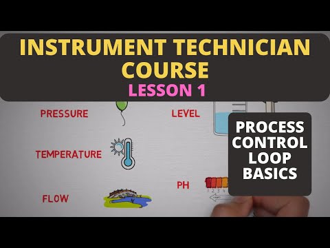
In todays video I am gonna discuss Control loop,Steps and principle involved in control loop which is very important in learning basic instrumentation
Now we will see What is Control Loop,
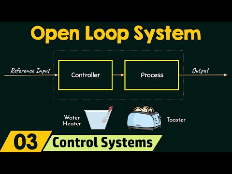
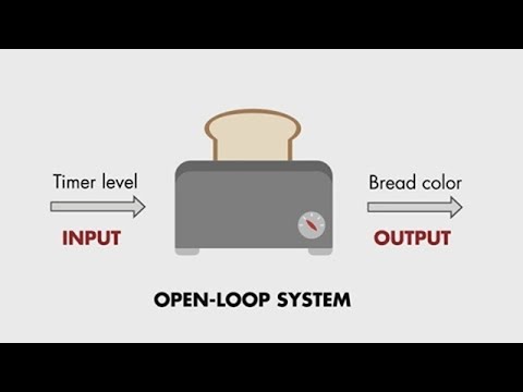
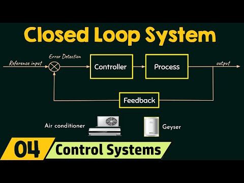
A control loop is a process management system designed to maintain a process variable at a desired set point. Each step in the loop works in conjunction with the others to manage the system. Once the set point has been established, the control loop operates using a four-step process.Sample control loop is shown
Now we will see steps and principle involved in control loop
There are four steps involved in control loop
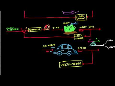
First step Sense : Measure the current condition of the process using a sensor, which can be a thermocouple or RTD transmitter.
Second step Compare : Evaluate the measurement of the current condition against the set point using an electronic PID controller.
Third step Respond : Reacts to any error that may exist between the measured temperature value and the temperature set point by generating a corrective pneumatic signal.
And the fourth one is Affect : Actuate the control valve that will produce a change in the process variable. The loop continually cycles through the steps, affecting the process variable (water temperature) in order to maintain the desired temperature set point.
We will know what is the Principle of control loop:
An electronic sensor (thermocouple, RTD or transmitter) installed at the measurement location continuously sends an input signal to the controller.
At set intervals, the controller compares this signal to a predefined set point. If the input signal deviates from the set point, the controller sends a corrective electric output signal to the control element.
This electric signal must be converted to a pneumatic signal when used with an air operated valve.
Using a I/P Transducer, which converts a 4 to 20 mA electric signal to a 3 to 15 PSI air signal and sends the respective air supply to the Control Valve Positioner.
The Valve Positioner adjusts the control valve stem position and regulates the flow through the control valve, accordingly the temperature controls. This loop repeats until controller achieves setpoint.
In my Previous video I discussed regarding Basics of Calibration, link for this is given in the description below
In todays video I am gonna discuss Control loop,Steps and principle involved in control loop which is very important in learning basic instrumentation
Now we will see What is Control Loop,
A control loop is a process management system designed to maintain a process variable at a desired set point. Each step in the loop works in conjunction with the others to manage the system. Once the set point has been established, the control loop operates using a four-step process.Sample control loop is shown
Now we will see steps and principle involved in control loop
There are four steps involved in control loop
First step Sense : Measure the current condition of the process using a sensor, which can be a thermocouple or RTD transmitter.
Second step Compare : Evaluate the measurement of the current condition against the set point using an electronic PID controller.
Third step Respond : Reacts to any error that may exist between the measured temperature value and the temperature set point by generating a corrective pneumatic signal.
And the fourth one is Affect : Actuate the control valve that will produce a change in the process variable. The loop continually cycles through the steps, affecting the process variable (water temperature) in order to maintain the desired temperature set point.
We will know what is the Principle of control loop:
An electronic sensor (thermocouple, RTD or transmitter) installed at the measurement location continuously sends an input signal to the controller.
At set intervals, the controller compares this signal to a predefined set point. If the input signal deviates from the set point, the controller sends a corrective electric output signal to the control element.
This electric signal must be converted to a pneumatic signal when used with an air operated valve.
Using a I/P Transducer, which converts a 4 to 20 mA electric signal to a 3 to 15 PSI air signal and sends the respective air supply to the Control Valve Positioner.
The Valve Positioner adjusts the control valve stem position and regulates the flow through the control valve, accordingly the temperature controls. This loop repeats until controller achieves setpoint.
 0:04:47
 0:06:58
 0:21:26
 0:09:13
 0:06:27
 0:04:17
 0:04:33
 0:07:11
 0:03:54
 0:12:53
 0:03:50
 0:05:46
 0:07:06
 0:08:22
 0:04:55
 0:05:28
 0:09:28
 0:04:57
 0:05:35
 0:14:00
 0:05:10
 0:01:28
 0:07:45
 0:21:51