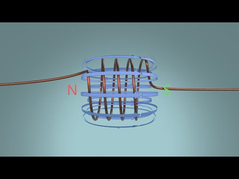
About Toroid inductors and magnetic field containment

preview_player
Показать описание
#141 In this video I look at the particularities of inductors wound on toroidal shaped cores. I look at the specific propriety of such cores to be superior from a magnetic field containment point of view, and what are the specific details that need to be taken into account to achieve this.

References:

Special Thanks to all my supporters on Patreon! Especially @afiskon, Ralf B., Paul Pr. Richard and Jonathan Alvarado!

If you liked this video be sure to check out my other videos and you can also subscribe to be up to date with all the new ones!
Рекомендации по теме
Комментарии
Автор

Late to the party ... But I did want to thank FesZ for this video. It nicely answered a years old question of mine about toroidal leakage.

Douglas_Blake_
Автор

Thanks for taking the time to show us. I read about it wiki years back but forgot most.

davidjackson
Автор

Just dropped by to say: solid series of videos, with the theoretical, the simulated, the implemented and the measured. Keep it up, all the best!

yashnu
Автор

thankyou for sharing stuff like
and please don't stop doing

BIGRIP
Автор

Amazing quality content, as always ! Thank you for your work.

fbach
Автор

Oooh yeah more magnetics videos!
One trick I've learn from amateur radio folks, when winding toroids for impedance matching autotransformers, is to wind the toroid until you get half way around the circle then loop the wire back to next to the start of the coil, and then continue winding around the other half of the circle (taking care to keep the winding direction the same), thereby creating two sections wound in opposite directions from the perspective of the circumferential coil so they cancel out - and also keeping the leads that form the ends of the inductor on opposite sides to reduce parallel capacitance created by them running parallel next to each other.

alaricsnellpym
Автор

40 years ago i had to wind a toroidal coil and it was a pain in the butt, Great video!

Liferoad
Автор

Thank you very much for creating all these awesome videos! I have already learned a lot from you and I think the way you explain and demonstrate your points is just perfect. Also, your selection of topics is great. Thanks again!

transfunktionator
Автор

For inductors in switching power supplies the parasitic inductors are likely to charge parasitic capacitors in the commutation mosfet that will create an oscillating RLC circuit,  rendering the power supply very inefficient and even unsafe. You can use an RC snubber to drain the parasitic inductor safely, preventing charging parasitic capacitors. The ( Spanish ) channel ACADENAS explains this really well, and today they will explain how to get values for the snubber. Maybe this channel could also make a short explanation for those who don't speak Spanish. Just a suggestion as unless one is a professional in electronics, most people are likely to use inductors for power supplies :)

pau
Автор

Hello again, I have just finished winding a mulit-layer step-up toriod pulse transformer. It was to have only two turns on the primary (for which I left about a 1-inch gap). The secondary was to have a couple hundred turns. I wound each layer to each end if the 1" gap, and was to place a layer of yellow mylar tape over each complete layer. For each layer, I used a separate piece of wire to avoid dealing with a very long wire for the entire secondary winding. To make it a continuous winding, I soldered the end of one winding to the start of the next.
I like to try using ODD numbers of layers so that the final secondary had it's ends on opposite sides if the primary gap. While winding the 4th layer, I discovered that I had wound it in the wrong direction! After thinking about it a while, I decided to 'jumper' one side of the 4th layer across the primary gap to the 4th layer to give the proper winding orientation of the 4th layer wrt the 3rd winding (BTW, I measure the inductance of the final two wires to make sure that it INCREASES with each winding). this seemed to correct the 4th layer WRT the first three. Now, I also got the expected increase in both inductance and spark length when the primary was pulsed. Also, this gave me a way to wind an EVEN number of layers and have the two end leads at opposite sides if the primary gap! In addition, I had several soldered taps, making many possible inductance selections.
Do you see anything undesirable here?
Thanks for all of your valuable information!!!

dalenassar
Автор

In DC to AC power inverters, designers often include an inductor in series with the low voltage side of the transformer to limit the no load current. It would be great to if you could do a video on how to design/size this inductor for optimum performance. I believe the idea may be to select an inductor that has a high impedance at idle (limiting the current) but one that quickly saturates at higher loads and thus does not effect the transformer performance.

yancymuu
Автор

Thanks for this wealth of information! I'm using a 2-wire bifilar winding on my torroid and was wondering if the bifilar direction is enough to cancel these effects, or if I will need shielding?

kevinclaypool
Автор

Thank you very much, I finally understood a lot)).

alexinal
Автор

When you run 7 wires in one direction and 7 in the opposite direction, why does this not cancel the magnetic field around the toriod, thus tending to eliminate the total lux in the core? (as seen at about timestamp 14:30 )

dalenassar
Автор

My output voltage is quite low on hand wound toroid transformer. I did match the frequency to source Ac, used proper core, and both wound in same direction. What is efficiency "percentage difference" of primary not wound exactly over secondary, just wound separate on core? It just looks visually better with 2 different colors insulation., at separate placements on core.

waterfuel
Автор

Thank you for uploading this video.
I would like to hear your opinion on the effects of coils in three dimensions

izysly
Автор

It would have been interesting to see what the inductance was for each case in addition to the leakage...

ats
Автор

Nice demo & explanation! Should the return-turn be placed on the ID of the toroid, or the OD, or somewhere in between? Does this matter (and is it tunable)? If you strictly look at the top-view of the initial turns, they trace a "15-pointed-star" - the average cross-section of the star would be somewhere between the ID and the OD..
You also mention leakage capacitance being an issue for bifilar windings. How does this work for the leadwires? You have twisted enameled wires for the leads - wouldn't these have orders-of-magnitude larger capacitance than the overlapping windings themselves? Could (e.g.) a coax or a UTP leadwire help in this regard?

AdityaMehendale
Автор

Can you please make a complete lecture about making planar transformers? The one which is made from PCB boards? Thanks.

ShopperPlug
Автор

Have a question regarding 7:28, what is the purpose of this two ended inductor?

RsBGroups