filmov
tv
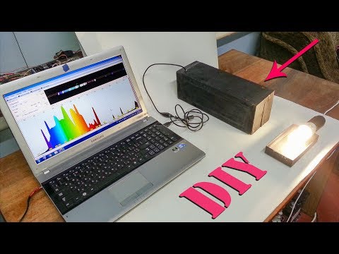
Creating a Spectrum Analyzer using an Arduino and a Non-Inverting Operational Amplifier

Показать описание
This is a summary of everything I learned trying to create a Non-Inverting Operational Amplifier circuit in order to feed an audio signal from a soundbar to an Arduino microcontroller so I could drive LED lights based off of the music playing.
Hope this is helpful and that I didn't make an egregious errors in the video lol.
Once I have the project setup inside my van I'll upload the source code I used.
Hope this is helpful and that I didn't make an egregious errors in the video lol.
Once I have the project setup inside my van I'll upload the source code I used.
 0:10:21
How to use a Spectrum Analyzer; techniques, controls, test methods, hints & tips
 0:06:45
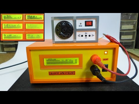
How to Make DIY Spectrometer | Optical spectrum analyzer | Light analysis
 0:04:57
Creating a Spectrum Analyzer using Lab View - ELCN100 - Laboratory CUFE
 0:04:35
Arduino-Based Spectrum Analyzer
 0:04:30
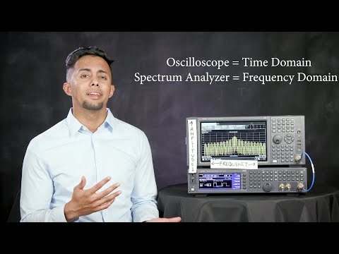
What is a Spectrum Analyzer and Measurements You Can Make - What the RF (S01E01)
 0:04:48
DIY Arduino audio signal spectrum analyzer with changeable visual modes
 0:11:31
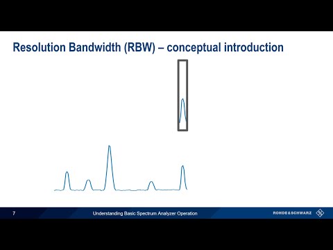
Understanding Basic Spectrum Analyzer Operation
 0:14:27
#597 Spectrum Analyzer Basics (part 1)
 0:09:29
Lindell Audio EQ825 - Plugin Alliance $20k mastering eq emulation || Mixing Playthrough (no talk)
![[AE]] How to](https://i.ytimg.com/vi/_UDgCbMEu68/hqdefault.jpg) 0:15:06
0:15:06
[AE]] How to make a LED matrix audio spectrum analyzer using Adobe After Effects
 0:16:13
Let's Build an Audio Spectrum Analyzer in Python! (pt. 1) the waveform viewer.
 0:00:31
How to use Frequency Analyzer on Flipper Zero
 0:16:20
#413 Your PC Soundcard is an Oscilloscope, a Signal Generator, and a Spectrum Analyzer (Arta, REW)
 0:00:15
DIY modular synth by ChatGPT : prototype spectrum analyzer with arduino & MSGEQ7 #synthdiy #syn...
 0:23:40
How to take your first measurement with a Spectrum Analyzer with UNI-T #UTS3021B #spectrumanalyzer
 0:22:22
ESP Spectrum Analyzer Code Review Part 1
 0:00:14
Build a DIY Spectrum analyser
 0:17:45
Build Your Own Spectrum Analyzer GNU RADIO Win10
 0:01:01
Don’t Make This Mistake When Using a Spectrum Analyzer
 0:13:54
How To Mix With a Spectrum Analyser - SPAN Tutorial
 0:14:58
Learn how to build a Spectrum Analyzer | Weekend Project | Easy to build |
 0:13:37
How to Build a Spectrum Analyzer with Lego Bricks & Discrete Electronics
 0:27:00
Creating a Spectrum Analyzer using an Arduino and a Non-Inverting Operational Amplifier
 0:03:30
Reason 4.0 How to make a Spectrum Analyzer Combinator (tutorial)
Комментарии