filmov
tv
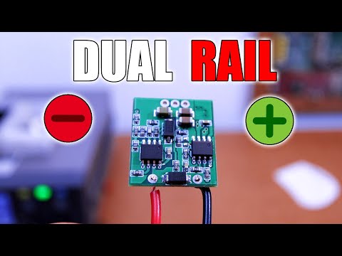
Dual Rail Supply - Different Options for Negative Voltage

Показать описание
🔥How to get for example +12 and -12V. Dedicated ICs, dual rail supply with center tapped transformer and much more. Learn how to get negaive voltage.
🔀LINKS
-------------------------------------
🤝SUPPORT
-------------------------------------
00:00 Intro
02:09
04:49
06:00
07:50
08:35
10:01 Thank You
Like share and subscribe to motivate me. Thank you
#electronics
#homemade
#circuits
 0:13:26
Dual Rail Supply - Different Options for Negative Voltage
 0:03:15
Monacor PS-605 dual rail bench power supply
 0:15:49
Single Rail vs Dual Rail PSU - It might be time to upgrade...
 0:11:43
How to Design a Low-Noise Dual Rail Voltage Supply
 0:30:32
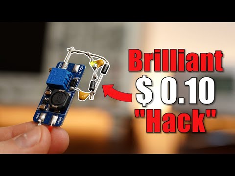
How To Get Dual Rail Supply from A Single Tap Transformer
 0:05:02
Single Rail vs Multi Rail PC Power Supplies as Fast As Possible
 0:09:54
Negative Voltages are more important than you think! So here is how to make them! EB#52
 0:05:57
Quick op amp rail splitter turning single power supply into DIY split aka dual supply electronzap
 0:00:20
Small Split Power Supply from a Single Rail - For Sensors, Opamp, LCD contrast and more
 0:00:17
Simple dual rail PSU from batteries. #psu #battery
 0:03:31
OPAMP Single/Dual Supply In Practice [Negative Rail and Positive Rail]
 0:16:22
Making a linear dual rail bench power supply 0 24V 0 2A
 0:06:11
DIY Dual Rail Power Supply
 0:39:22
Build a Small Dual Rail Linear Bench Power Supply.
 0:04:40
WHICH ONE SHOULD YOU BUY ?? DUAL RAIL VS MULTI RAIL POWER SUPPLY EXPLAINED
 0:05:47
LM338 Dual Rail Supply Experiment
 0:05:56
Dual Power Supply (DC Rail Splitter) For Op Amps and Audio Amplifiers
 0:03:23
Dual Rail 24 0 -24 V power supply DIY
 0:09:38
The cheapest and simplest way of getting a negative voltage rail
 0:03:20
1000W Dual Rail Power Supply for Audio Amplifier
 0:40:54
Build Rebellion - Audio Amp - Ep2. Dual Rail Voltage Supply
 0:05:52
TL494 Dual Rail Power Supply 12V to 50-0-50V
 0:08:26
Op amp virtual ground rail splitter circuit using JRC4558D schematic diagram by electronzap
 0:00:10
Amplifier power supply . Upto 45v 0 45v dual rail 18800uf in each rail . 15 0 15 and 5v regulated .
Комментарии