filmov
tv
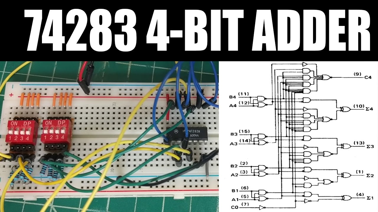
Tutorial | Building the 74283 74HC283 4 BIT ADDER
Показать описание
 0:05:32
Tutorial | Building the 74283 74HC283 4 BIT ADDER
 0:04:00
Logic Tutorial | Building the 74283 74HC283 4 BIT ADDER
 0:15:34
4-Bit Adder built from logic gates
 0:05:17
4 Bit Full Binary Adder & 74283 IC
 0:04:28
Lab2- 5 bit Adder with Full Adder and 74283 chip
 0:19:32
Die Zeit vor programmierbaren Mikrocontrollern - Addieren mit dem IC 74283
 0:03:54
Full adder/Subtactor using 74283
 0:03:22
EveryCircuit - 4 bit Binary Adder || Tutorial 6
 0:08:39
Build 4bit Computer/Adder | How to | SdevElectronics
 0:03:37
How to actually build a 4 bit adder (on a breadboard)
 0:33:42
Building an 8-bit register - 8-bit register
 0:04:11
7483 4 Bit Adder using Proteus
 0:10:05
BCD Adder
 0:26:35
STLD lab 4: IC adders (74283) using Multisim
 0:11:53
Full Adder
 0:08:46
Proteus Rangkaian penjumlah Adder 16 Bit menggunakan IC 74283
 0:02:55
Verificação do funcionamento de um circuito somador utilizando o CI 74283
 0:06:51
4 bit calculator built using individual transistors
 0:07:39
Learn how computers add numbers, 4 bit adder circuit
 0:00:20
Full Adder Circuit
 0:00:11
4-bit Binary Counter
 0:05:46
#20. FULL ADDER || ON BREADBOARD || STEP BY STEP
 0:00:35
DIY Arduino: Build Your Own Full Adder and Unleash the Power of Digital Logic
 0:09:33
Simulação: Somatório binário com o CI 74283
Комментарии