filmov
tv
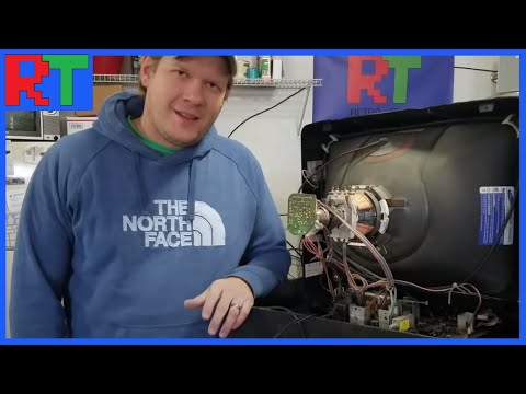
Cathode ray tube disassembly and explanation

Показать описание
I cut open a cathode ray tube (picture tube, or CRT) and explain the internal parts and their function.
 0:12:14
Cathode ray tube disassembly and explanation
 0:02:12
Tech Support: Safely Discharge CRT Monitor
 0:11:09
Safe CRT Monitor Disassembly
 0:10:25
Crt Tv Teardown
 0:01:08
Disassembling a Sony 30' CRT Television in 68 Seconds - Time Lapse
 0:00:13
how to remove the fbt/flyback cop on a CRT tv tube #tips #method #tutorial #remove #cop #fbt
 0:00:15
How to remove the copper yoke from a CRT TV - #diy #recycle #howto #scrap #diy #disassembly #copper
 0:17:21
CRT Safety - The Consumer TV Version - Cathode Ray Tube
 0:01:47
CRT monitor disassembly tool
 0:22:55
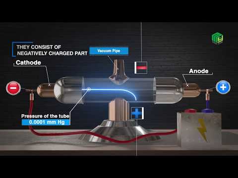
Cathode Ray Tubes: invention, explanation and experiments
 0:01:58
Cathode Ray Tube | www.MyInterAcademy.com
 0:00:15
Cathode ray
 0:20:19
1980's Cathode Ray Oscilloscope Teardown - The Electronics Inside
 0:10:54
CRT Tube Swap: The Repair Tutorial You've never seen!
 0:14:51
How To Service A CRT Monitor
 0:17:02
EEVblog #524 - Vignetting on a Cathode Ray Tube
 0:08:40
Panasonic CRT Monitor Teardown
 0:07:14
Sony Trinitron CRT TV Discharge and Tear Down
 0:11:08
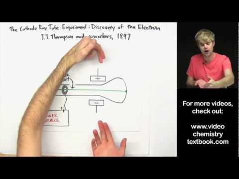
Discovery of the Electron: Cathode Ray Tube Experiment
 0:00:09
Let See What is inside the CRT (colour Picture Tube)#shorts #youtubeshorts
 0:00:39
Inside a CRT Tube (electron gun) #crt #crtgaming #crttvrepairing
 0:00:16
CRT tv glass breaking part 7 voice #asmr
 0:09:32
How to Disassemble a CRT Television
 0:15:12
Manual dismantling of a CRT TV
Комментарии