filmov
tv
LM317 Current Boosting Circuits [2N3055, MJ2955]

Показать описание
LM317 Current Boost Circuits using 2N3055 and MJ2955
======================================
======================================
======================================
======================================
#LM317
LM317 is one of the most popular adjustable regulator chips. The output voltage of the regulator can be adjusted from 1.25V to 35V. However, the chip can deliver currents up to 1.5A which is not enough for some power applications. In this article, I will discuss two methods of LM317 current boosting, using power PNP and NPN pass transistors.
According to the LM317 datasheet: “The LM317 [1, 2] device is an adjustable three-terminal positive-voltage regulator capable of supplying more than 1.5 A over an output-voltage range of 1.25 V to 37 V. It requires only two external resistors to set the output voltage. The device features a typical line regulation of 0.01% and a typical load regulation of 0.1%. It includes current limiting, thermal overload protection, and safe operating area protection. Overload protection remains functional even if the ADJUST terminal is disconnected.”
This information proves to us that this cheap 3-terminal device is suitable for many applications but it comes with a drawback for power applications and that is the limitation of the regulator’s output current handling (1.5A in the best conditions). This problem can be solved using a pass power transistor.
Current Boosting Using a PNP Power Transistor (MJ2955)
Figure-1 shows the schematic diagram of the circuit. This is an adjustable high current regulator circuit that the output voltage can be adjusted using a 5K potentiometer.
The 10R resistor defines the Turn-On time of the pass-transistor and by the way, it defines how much current should passe through the LM317 and MJ2955 [3, 4]. Based on this parameter, the power rate of the resistor must be calculated. 1N4007 is a protective diode and 270R resistor provides the necessary ADJ pin’s current. As mentioned earlier, the 5K potentiometer defines the output voltage. 1000uF, 10uF, and 100nF capacitors have used to reduce noises. Don’t forget to install the transistor on a big heatsink.
[A-2] Current Boosting Using an NPN Power Transistor (2N3055)
Figure-2 shows the schematic diagram of the circuit. The 10K resistor at the output draws a small amount of current to avoid the floating output and it helps to stabilize the output voltage. Here 2N3055 [5, 6] plays the role of pass-transistor also.
======================================
======================================
======================================
======================================
#LM317
LM317 is one of the most popular adjustable regulator chips. The output voltage of the regulator can be adjusted from 1.25V to 35V. However, the chip can deliver currents up to 1.5A which is not enough for some power applications. In this article, I will discuss two methods of LM317 current boosting, using power PNP and NPN pass transistors.
According to the LM317 datasheet: “The LM317 [1, 2] device is an adjustable three-terminal positive-voltage regulator capable of supplying more than 1.5 A over an output-voltage range of 1.25 V to 37 V. It requires only two external resistors to set the output voltage. The device features a typical line regulation of 0.01% and a typical load regulation of 0.1%. It includes current limiting, thermal overload protection, and safe operating area protection. Overload protection remains functional even if the ADJUST terminal is disconnected.”
This information proves to us that this cheap 3-terminal device is suitable for many applications but it comes with a drawback for power applications and that is the limitation of the regulator’s output current handling (1.5A in the best conditions). This problem can be solved using a pass power transistor.
Current Boosting Using a PNP Power Transistor (MJ2955)
Figure-1 shows the schematic diagram of the circuit. This is an adjustable high current regulator circuit that the output voltage can be adjusted using a 5K potentiometer.
The 10R resistor defines the Turn-On time of the pass-transistor and by the way, it defines how much current should passe through the LM317 and MJ2955 [3, 4]. Based on this parameter, the power rate of the resistor must be calculated. 1N4007 is a protective diode and 270R resistor provides the necessary ADJ pin’s current. As mentioned earlier, the 5K potentiometer defines the output voltage. 1000uF, 10uF, and 100nF capacitors have used to reduce noises. Don’t forget to install the transistor on a big heatsink.
[A-2] Current Boosting Using an NPN Power Transistor (2N3055)
Figure-2 shows the schematic diagram of the circuit. The 10K resistor at the output draws a small amount of current to avoid the floating output and it helps to stabilize the output voltage. Here 2N3055 [5, 6] plays the role of pass-transistor also.
 0:09:57
LM317 Current Boosting Circuits [2N3055, MJ2955]
 0:06:26
Current Boost LM317 Adj. Power Supply
 0:10:43
#548 LM317 with Transistor for more Current
 0:03:19
Increase Output DC Current Using 2N3055 Transistor
 0:02:39
Constant 12v/5 Amps DC Supply Circuit Make very Easy | 2N3055 Transistor
 0:00:37
LM317 with 2n3055 Adjustable Voltage Regulator Circuit
 0:11:34
DC Voltage and amp Adjustable power Supply, Simple DC voltage regulator
 0:15:23
Adjustable LM317 High Powered Current Source
 0:09:56
Simple Adjustable DC voltage power supply, Voltage regulator DIY
 0:09:06
DIY LM317 Parallel 2N3055 Power Supply
 0:07:33
Constant Current Regulator using LM317 | CCR | LM317 as a current regulator
 0:05:03
Adjustable Power Supply 2n3055 lm317
 0:02:16
1.5v to 25v 5-Ampere DC Voltage Controller | Linear dc voltage regulator | LM317 voltage regulator
 0:03:33
12V 5A regulated power supply with 2N3055 current booster with 7812 7805 7824 voltage regulator
 0:00:58
Adjustable Voltage Regulator Using 2N3055 | 0-48V 15A
 0:17:28
DIY - High voltage linear regulator based on the LM317 - Part 2
 0:00:50
How To Make 10amp Voltage Regulator | LM317T Ampare Increase. MJE3055
 0:02:54
DIY 1.2-30V 5A variable power supply (LM317 and 2n3055)
 0:00:30
2n3055 | adjustable voltage regulator circuit | #shorts
 0:00:48
Adjustable power supply #shorts #youtubeshorts
 0:00:13
How To make LM317 Ic based voltage regulator
 0:00:59
Adjustable Voltage Regulator 0-40V 12A
 0:03:17
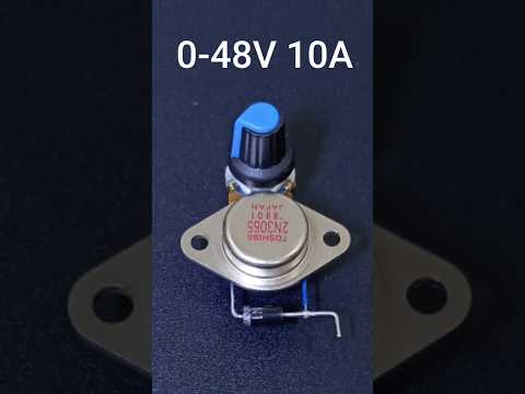
Adjustable Voltage Regulator Using 2N3055 Transistor | 0-48V 10A
 0:05:06
Uncover the Magic of a 1-35V 15A Variable Power Supply!
Комментарии