filmov
tv
Productivity 1000 Series PLC Modbus TCP Ethernet Communication

Показать описание
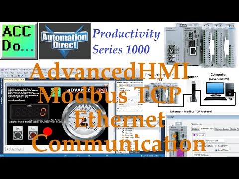
The productivity series of PLCs comes with 4 built-in communication ports for easy connectivity to your PC or various industrial networks. Ethernet protocols like Modbus TCP can be utilized with the RJ45 port on this PLC. Modbus TCP is an open (published) protocol that uses the Server (Master) / Client (Slave) architecture. It’s a very common protocol used in industrial automation controls.
We will be using the RJ45 (Ethernet) port to communicate to a Click PLC. Modbus TCP will be the protocol used on this Ethernet communication media. The Productivity 1000 PLC will be the server and the Click PLC will be the client. We will be creating a network between the two PLC units. A heartbeat will be used so if communications are lost, the server (slave) will know. The throughput time will be timed by using a small program in the Click PLC. You will soon see how the Productivity Series of PLCs is the best way to handle communication with other devices. Let’s get started.
More information can be obtained on our website. This includes all of the links mentioned in this video.
00:00 Productivity 1000 Series PLC Modbus TCP Ethernet Communication
01:33 Click PLC Modbus TCP Setup Port
02:45 Click PLC Modbus Addresses
04:13 Productivity 1000 Modbus TCP Port Setup
05:00 Hardware - Click and Productivity 1000 PLCs
05:40 Productivity Ladder Logic PLC Program
10:24 Click Ladder Logic PLC Program
14:40 Solo Communications
Here are some previous posts in this Productivity 1000 PLC Series. A full list can be obtained at the following location:
System Hardware
Installing the Software
Establishing Communication
First Program
Documenting the Program
Monitoring and Testing the Program
Online Editing and Debug Mode
Video
Numbering Systems and Tag Database
Video
Contact and Coil Instructions
Video
Timer Instructions
Video
Counter Instructions
Video
Math Instructions
Video
Data Handling Instructions Part 1
Video
Data Handling Instructions Part 2
Video
Array Functions Part 1
Video
Array Functions Part 2
Video
Array Functions Part 3
Video
Program Control
Video
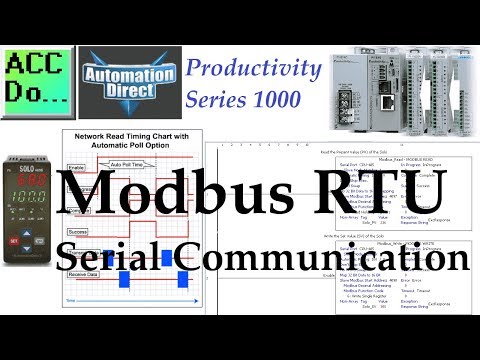
Modbus RTU Serial Communication
Video
There are several reasons why we are using the Productivity 1000 Series Controller. Here are just a few.
- 50MB user memory - Can handle very complex applications easily.
- 4 built-in communication ports – Easy connectivity to your network.
- Data logging up to 32 GB on a microSD card
- Add up to 8 IP modules to communicate to your field sensors. This will give you a total of 128 discrete IO points or 32 analog IO channels.
- Free Software and 30 days of free training with every CPU from Automation Direct.
- Interactive PLC Configuration Tool
- Tag Names
- Auto-discovery IO – Physical I/O tags will be generated based on each module’s position in the base.
- I/O Modules have QR codes under the wiring cover. This can be scanned so you can have the latest specifications/wiring diagrams for the module.
- Limitless PID – Autotuning – Individual or Cascade Mode - etc
- Web Server and Mobile Access
- Advanced Software instruction set
The Productivity 1000 series of programmable logic controllers currently has all of these features built into the P1-540 CPU.
This CPU (Central Processing Unit) is also known as MPU (Multi-Processing Units) because of its communication capabilities.
We will be using the RJ45 (Ethernet) port to communicate to a Click PLC. Modbus TCP will be the protocol used on this Ethernet communication media. The Productivity 1000 PLC will be the server and the Click PLC will be the client. We will be creating a network between the two PLC units. A heartbeat will be used so if communications are lost, the server (slave) will know. The throughput time will be timed by using a small program in the Click PLC. You will soon see how the Productivity Series of PLCs is the best way to handle communication with other devices. Let’s get started.
More information can be obtained on our website. This includes all of the links mentioned in this video.
00:00 Productivity 1000 Series PLC Modbus TCP Ethernet Communication
01:33 Click PLC Modbus TCP Setup Port
02:45 Click PLC Modbus Addresses
04:13 Productivity 1000 Modbus TCP Port Setup
05:00 Hardware - Click and Productivity 1000 PLCs
05:40 Productivity Ladder Logic PLC Program
10:24 Click Ladder Logic PLC Program
14:40 Solo Communications
Here are some previous posts in this Productivity 1000 PLC Series. A full list can be obtained at the following location:
System Hardware
Installing the Software
Establishing Communication
First Program
Documenting the Program
Monitoring and Testing the Program
Online Editing and Debug Mode
Video
Numbering Systems and Tag Database
Video
Contact and Coil Instructions
Video
Timer Instructions
Video
Counter Instructions
Video
Math Instructions
Video
Data Handling Instructions Part 1
Video
Data Handling Instructions Part 2
Video
Array Functions Part 1
Video
Array Functions Part 2
Video
Array Functions Part 3
Video
Program Control
Video
Modbus RTU Serial Communication
Video
There are several reasons why we are using the Productivity 1000 Series Controller. Here are just a few.
- 50MB user memory - Can handle very complex applications easily.
- 4 built-in communication ports – Easy connectivity to your network.
- Data logging up to 32 GB on a microSD card
- Add up to 8 IP modules to communicate to your field sensors. This will give you a total of 128 discrete IO points or 32 analog IO channels.
- Free Software and 30 days of free training with every CPU from Automation Direct.
- Interactive PLC Configuration Tool
- Tag Names
- Auto-discovery IO – Physical I/O tags will be generated based on each module’s position in the base.
- I/O Modules have QR codes under the wiring cover. This can be scanned so you can have the latest specifications/wiring diagrams for the module.
- Limitless PID – Autotuning – Individual or Cascade Mode - etc
- Web Server and Mobile Access
- Advanced Software instruction set
The Productivity 1000 series of programmable logic controllers currently has all of these features built into the P1-540 CPU.
This CPU (Central Processing Unit) is also known as MPU (Multi-Processing Units) because of its communication capabilities.
 0:19:16
 0:12:52
 0:16:51
 0:11:09
 0:17:48
 0:15:55
 0:18:44
 0:05:39
 0:06:15
 0:06:15
 0:23:27
 0:03:46
 0:10:41
 0:11:40
 0:00:59
 0:16:06
 0:11:11
 0:14:39
 0:16:01
 0:03:28
 0:21:05
 0:01:00
 0:19:28
 0:08:30