filmov
tv
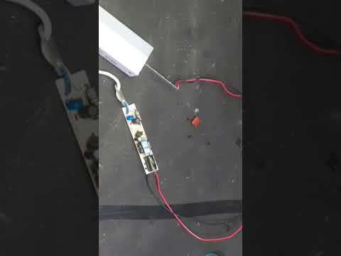
SMD Slow Flash LEDs and a PCB

Показать описание
SMD Slow Flash LEDs and a PCB
The LEDs are great, but my creation of the custom 0606 pads did not go as planned.
*************************************************************************
*I will get a small commission and it costs you nothing. *
*************************************************************************
HEY YOU ABOUT TO POST SOMETHING STUPID:
One of the symptoms is that it causes fluid retention, mostly in the hands, feet/ankles, and face..
--------------------------------------------------------------------------------------------------------------------
Amazon Store:
---------------------------------------------------------------------------------------------------------------------
Donation:
---------------------------------------------------------------------------------------------------------------------
Gear I use:
Bench O'Scope:Hantek DSO2D15
SMD Slow Flash LEDs and a PCB
 0:00:12
0807 RGB SMD LED fast flashing 0805 RGB slow flashing LED diode built-in IC, factory sell
 0:01:54
Slow Flash SMD LED
 0:00:31
NE555 Projects | NE555 LED Flasher | Circle LED Light | Round LED Light | Running Light Effect |
 0:00:33
Simple blinking LED circuit with BC 547 - Strobe light
 0:00:23
C6861 - SMD Flashing Initials Kit
 0:01:00
G26150 - (Pkg 5) Rare Tiny SMD White Flashing LED
 0:00:18
How to fix LED lights with a pencil is an idea you would never think of🇬🇧🇲🇫🇺🇸💯✅😉💪💡💡...
 0:00:13
How to soldering 0805 SMD LED light shorts
 0:00:11
RGB Led Light #uzintech #shorts #led #light
 0:00:13
G26151 - (Pkg 5) Rare Tiny SMD Blue Flashing LED
 0:00:09
Fast flashing Built-in IC 2835 RGB SMD LED slow flashing Light full color LED For Cars lamp
 0:00:13
0805 flashing SMD LED
 0:00:14
Flashing LEDs Test SMD
 0:00:59
how to repair LED bulb
 0:00:49
Simple LED Blink Circuit using BC547 Transistor: Breadboard Project
 0:00:16
HOW TO INSTALL M6 LED ON Honda cd 70 | M6 MOTOLED LAGANEY KA MUKAMAL TARIKA On Itthad auto
 0:01:52
Super LED Blinking With 1 Transistor | Make 12-24 Volt Flashing Lights
 0:00:09
RGB LED - SMD Light Flash
 0:00:16
Led Tubelight Repair | led tube light blinking problem repair | led tubelight ka driver repair
 0:06:35
led smd blinking repair
 0:01:00
How To Re-use An Old Smd LED Board #shorts
 0:00:47
LED Beacon 80 SMD 3 patterns flash (Bolt)
 0:00:32
0805 RGB Color Changer Fast to Slow
Комментарии