filmov
tv
Mini Induction Heater

Показать описание
This video shows how I build a ZVS driver to power a small induction heater than can make pieces of metal weighing ~1 gram or less glow red hot. The circuit takes in 10-16V and the final variant shown in this video oscillates at about 160 kHz. I also show how this circuit can be used to drive a flyback transformer.
This is a very modestly powered circuit, but the advantage of a ZVS driver is that it can be scaled up to tens of kW without much of a problem. The voltage on the coil (and the MOSFET V-DS) is about 3 times the input voltage, so to use higher voltages of say, 36 or 48V, I would need MOSFETs rated for a higher V-DS like an IRF250 or IRF460.
NOTE: My statement about inductance not changing is inaccurate. Inserting a ferromagnetic object into the coil *does- increase the inductance and reduce the frequency.
Hardware used:
IRF44 Mosfet
1N4148 Diode
5.6V Zener Diodes
400 Ohm Gate Resistor
10k Gate pulldown resistor
1 uF 630V Polypropylene film capacitor
Music:
Kevin MacLeod - George Street Shuffle
Serge Pavkin - Fractal
 0:08:20
Mini Induction Heater
 0:04:45
MINI INDUCTION HEATER REVIEW
 0:21:39
Mini Induction Heater from Banggood | Review and Test
 0:07:25
Amazon TaiShi 1000W 110V Magnetic Induction Heater Kit Review
 0:01:18
Mini-Ductor® Venom®: Handheld Induction Heater Animated Product Overview
 0:00:43
DIH 1500W Portable Min Induction heating pistol tool for remove rusty nut
 0:05:58
Top 5 Best Mini Induction Heater 2022 | aliexpress
 0:15:47
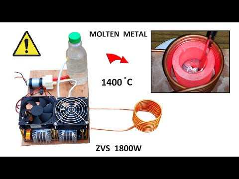
12v to 48v 50A ZVS Induction Heater for Melting Metals - 1800W
 0:18:49
ALL NEW ITEMS FROM TOPDON, GRIPEDGE, AND INDUCTION INNOVATIONS!!!
 0:11:23
120w 12v ZVS Induction Heating Power Supply Module
 0:06:29
How does Induction Heating Work? || DIY Induction Heater Circuit
 0:07:11
5V-12V 120W Mini ZVS Induction Heating Board Flyback Driver Heater DIY Cooker + Ignition Tesla Coil
 0:06:04
Top 5 Best Mini Induction Heater Review | best mini induction heater
 0:08:42
Heat Rusty Bolts RED-HOT in Seconds - Mini-Ductor Venom MDV-777
 0:11:57
Mini-Ductor II - Flameless Heat System - MD-700 - MADE IN USA
 0:05:04
120W Induction Heater - Overview and 12v testing │HL-EXPERIMENT
 0:27:32
Mini-Ductor Venom HP
 0:06:28
Single Mosfet High powerful induction Heater |Build 5v DC Powerful induction heater
 0:01:52
Can I remove 40 year old seized bolts using an induction heater?
 0:05:41
$2 Induction Heater 12V from Aliexpress
 0:08:04
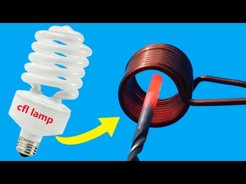
This Simple Trick Turns Old CFL Lamps Into Awesome Induction Heaters
 0:00:36
Induction Innovations' Mini-Pad Attachment Demo
 0:01:18
Mini-Ductor® Venom® HP - The Highest Powered Mini-Ductor Available
 0:00:15
Mini-Ductor Venom Portable Induction Heater with Coil #automobile #mechanictip #car #tools
Комментарии