filmov
tv
SDR Tranceiver - Part 5 More Troubleshooting

Показать описание
More Receiver troubleshooting (without much luck unfortunately)
0:00 Probing before Audio Switch
2:00 Adding more decoupling caps
3:30 Replacing the FST3253
5:26 Byassing the Audio Switch
6:55 Looking at the ESP32 Header
8:44 New header board arrive - does it fix the problem?
0:00 Probing before Audio Switch
2:00 Adding more decoupling caps
3:30 Replacing the FST3253
5:26 Byassing the Audio Switch
6:55 Looking at the ESP32 Header
8:44 New header board arrive - does it fix the problem?
 0:10:48
SDR Tranceiver - Part 5 More Troubleshooting
 0:08:48
Homebrew Teensy SDR Transceiver Part 5 - Transmit experiments
 0:15:49
Magnis SDR - Part 5 Receiver
 0:00:30
A New Xiegu Transceiver #xiegu #hamradio #transceiver
 0:10:46
SDR Transceiver - Part 7 New Board
 0:00:16
HF SDR Transceiver, Low Power Emission, HF Communication, YC2DB, 9N1CA, #hamradio #radio #shorts
 0:00:26
Exploring the uSDX Plus
 0:00:27
Homebrew SDR Transceiver - LU3EBW
 0:11:15
SDRPlay nRSP-ST Networked Receiver: Unboxing and Testing
 0:00:24
The RTL-SDR a relatively cheapr SDL receiver
 0:08:05
USDX USDR+ 8 Band HF SDR Transceiver
 0:00:16
Malachite DSP SDR 1.10d Radio Receiver V5 With Optional Board Metal Case 5000mAh AM CW SSB NFM WFM
 0:00:16
SDR receiver Malahit test.
 0:19:55
Could This Be The BEST SDR Receiver? Using PiHPSDR & SDRPlay RSPdx
 0:00:15
SDR HackRF Fix with Noise | #SDR #HackRF #Radio
 0:00:16
baofeng fm transceiver #sdr #baofeng #fm #radio
 0:14:50
The Beginners Guide To The Radioberry HF SDR Transceiver Pi Hat
 0:00:15
W4KWS QRP DX S51DX Review new Icom IC-705 Ham Radio Adventure @W4KWS
 0:24:07
The ONLY SDR Software you’ll ever need.. (Software Defined Radio)
 0:14:51
GUOHETEC PMR-171 ALL MODE - HF/VHF/UHF SDR TRANSCEIVER
 0:03:49
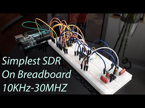
Simple SDR receiver (10kHz-30MHz)
 0:00:19
The M17 Revolution: Transforming How We Communicate
 0:00:11
YAESU FT 710 HF TRANSCEIVER #hamradio #shorts #ft710 #yaesu
 0:00:29
AirSpy SDR# FM cochannel Canceller Some kind of magic
Комментарии