filmov
tv
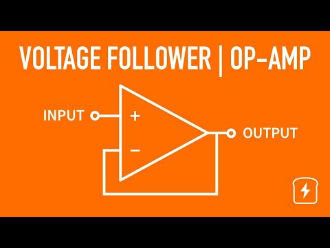
Voltage Follower - Operational Amplifier | Basic Circuits | Electronics Tutorials

Показать описание
Operational amplifiers, or op-amps, have a variety of popular configurations but one of the most often used is as a voltage follower. In this video, Josh goes over the concept behind a voltage follower, where and why you'd need it, and does a practical example showing how it affects the output voltage of a high-impedance source.
Parts of the video:
0:00 Introduction
0:36 What's the point of a voltage follower?
0:54 High- versus low-impedance outputs
3:47 Simulating a high-impedance output
4:38 Setting up the op-amp voltage follower
6:01 Trade-offs
8:21 The toast will never pop up
CircuitBread is joining the fight to help people more easily learn about and use electronics. With an ever-growing array of equations, tools, and tutorials, we're striving for the best ways to make electronics and electrical engineering topics more accessible to everyone. Come learn electronics with us!
Connect with CircuitBread:
 0:08:44
Voltage Follower - Operational Amplifier | Basic Circuits | Electronics Tutorials
 0:03:30
Voltage Follower Explained: Buffer Amplifier for Electrical Isolation | Operational Amplifier
 0:06:26
Voltage Follower - Operational Amplifiers - Application of Electronics Class 12
 0:01:35
op amp voltage follower
 0:05:50
Op-amp as Voltage Follower or Buffer Amplifier (English)
 0:01:28
#34 OPAMP as voltage follower
 0:11:40
Operational Amplifier: Non-Inverting Op-Amp and Op-Amp as Buffer (Op-Amp as Voltage Follower)
 0:09:35
Voltage Follower using OpAmp (Basics, Definition, Circuit & Uses) Explained | Analog Electronics
 0:03:05
5. Voltage Follower
 0:02:25
VOLTAGE FOLLOWER CIRCUIT USING OP-AMP | Hindi
 0:10:09
Op amp Voltage Followers Answers to Questions
 0:03:28
Opamp Voltage Follower Circuit| Circuit Diagram | Breadboard Wiring
 0:07:57
Operational Amplifiers No 3, Voltage Followers
 0:04:43
Voltage Follower Op-Amp
 0:09:24
VOLTAGE FOLLOWER || OPAMP AS VOLTAGE FOLLOWER || VOLTAGE FOLLOWER USING OPAMP || WITH EXAM NOTES ||
 0:05:17
How to Design a Op Amp Buffer Circuit? Voltage follower | Op Amp as a buffer
 0:07:27
The Operational Amplifier - Part V: Voltage Follower
 0:06:48
Voltage follower Unity Gain Buffer - Operational Amplifier and 555 Timer - Industrial Electronics
 0:04:08
VOLTAGE FOLLOWER
 0:02:41
Why add resistors to the voltage follower of the operational amplifier?--Utsource
 0:06:32
Voltage Follower in OP-Amp | Hindi | [Lec 4]
 0:00:08
How To Make Voltage Follower Using OP-Amp
 0:03:26
Op Amps - Basics / Voltage Follower
 0:00:22
OPAMP as Voltage Follower
Комментарии