filmov
tv
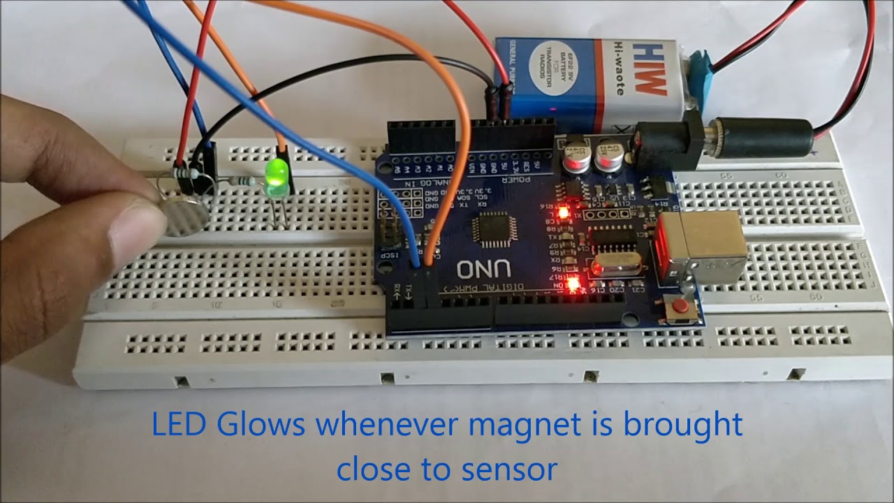
Hall Effect Sensor interfacing with Arduino
Показать описание
 0:01:50
Hall effect sensor interfacing with Arduino
 0:04:50
How to use LINER MAGNETIC HALL SENSOR | LINER MAGNETIC HALL SENSOR with Arduino Nano (With code)
 0:00:54
Hall Effect Sensor interfacing with Arduino
 0:00:15
DRV5023 HALL EFFECT SENSOR INTERFACING
 0:04:15
asc712 hall effect sensor interfacing with Arduino for dc current measurement
 0:11:25
Introduction to head-on applications
 0:06:02
Arduino hall effect sensor with interrupts
 0:04:34
Hall Effect Sensor Tutorial with Arduino
 0:01:48
KY-003 Hall magnetic sensors module
 0:09:48
NI myRIO: Hall-effect sensor
 0:09:10
Magnetic Hall effect sensor Arduino programming and interfacing
 0:05:40
Interfacing KY-024 Hall Effect sensor with Arduino | DigitSpace.com
 0:05:22
Designing with Hall-effect sensors: Human machine interface (HMI) rocker switch
 0:00:15
Magnetic Field Sensor Circuit Using A324 Hall Effect Sensor
 0:27:00
New Product Update: 3D linear Hall-effect sensor
 0:04:01
Allegro A1104 Hall Effect Sensor Interface
 0:00:36
Hall Sensor Interfacing with ATmega16 AVR Microcontroller
 0:08:59
Introduction to Hall-effect position sensing
 0:00:44
Interfacing Hall Effect Sensor IC Allegro A1104E with an OPAMP
 0:08:15
Hall effect sensor with Arduino
 0:00:32
What is the Hall effect? #slkor #semiconductor
 0:04:12
Si72xx Hall Effect Sensor Demos - from Silicon Labs
 0:00:16
Hall Effect Sensor 🔥 Magnetic Sensor 🧲 #shorts #viralvideo #reels #electronic #electroeshu #diy...
 0:06:09
Designing robots with Hall-effect sensors
Комментарии