filmov
tv
Light Animation Control Using Arduino And MATLAB Based GUI

Показать описание
This is project carried out by a team of five students from OBAFEMI AWOLOWO UNIVERSITY (OAU) ILE-IFE:
Alabi Emmanuel Oluwatimileyin, Orisaremi Madonna Megan,
Olagunju Alex Israel,
Oyeyemi Oluwatobiloba Ezekiel,
Usman Ahmad Juwon,
Under the supervision of Dr. Akinwale..
LIGHT ANIMATIONS are visually appealing and hence widely used for advertising purposes and other lots of things. One major use of it on this campus is for welcome greetings at every hall of residence entrance here on OBAFEMI AWOLOWO UNIVERSITY (OAU) ILE-IFE CAMPUS.
In this project, we present a MATLAB-based graphical user interface (GUI) approach to control the glowing pattern of a number of light-emitting diodes (LEDs).
This project creates five different lighting patterns including ring counter and Johnson counter by clicking appropriate pushbuttons in the GUI. The blinking speed of LEDs can also be controlled using fast, normal and slow pushbuttons in the GUI.
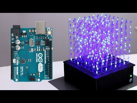
The circuit for controlling and connection light animations consists of an Arduino Uno board, eight LEDs and eight 1-kilo-ohm resistors.
Arduino Uno is an AVR ATmega328P microcontroller-based development board with six analogue input pins and 14 digital input/output (I/O) pins. The microcontroller has 32kB of ISP flash memory, 2kB RAM and 1kB EEPROM. The board provides serial communication via UART, SPI and I2C. The microcontroller can operate at a clock frequency of 16MHz.
In this project, digital I/O pins 3 through 10 of the Arduino are configured as output pins and used to control the illumination of eight LED.
When a pushbutton corresponding to a particular pattern is pressed in the GUI, it executes the corresponding callback function in the source program (group8_project11.m). The callback function executes program statements corresponding to that pattern and sends High or Low control signals to appropriate pins of the Arduino in order to create the desired glowing pattern. Eight series-connected 1-kilo-ohm resistors limit current flow through LEDs.
Download ‘‘MATLAB and Simulink Support package for Arduino Hardware’ package from MathWorks website or install directly from MATLAB by clicking on the “Add-ons icon -- Get hardware support packages” on the interface and search for the support package.
Connect the Arduino Uno board to your PC. MATLAB will automatically detect the Arduino board. From Device Manager, note the COM port number at which the Arduino Uno board is connected or type “a = Arduino “on the MATLAB command window to display Arduino properties. Click on Add-ons again to install the support package and follow the instruction to install it. After installation, it will request to program the board. Click the right port number and Program the board (i.e. the port number you noted earlier “COM__”).
This GUI application program has been developed in R2021a version of MATLAB.
After installing this MATLAB version in your PC:
Open the source code file (group8_project11.m) for this project. Edit the line “a=Arduino(‘COM5)’’ (in this project the line corresponding to the code is line 78), to the COM port number in your PC where the Arduino Uno board has been connected to. When you run the project file, MATLAB will try to communicate with the board. After successful communication is established, you can control LEDs by pressing the corresponding pushbuttons in the GUI.
NOTE: ALL STEPS ABOUT INSTALLING MATLAB SUPPORT PACKAGE IS FOR MATLAB R2021a
VERSION USED IN DOING THIS PROJECT
Alabi Emmanuel Oluwatimileyin, Orisaremi Madonna Megan,
Olagunju Alex Israel,
Oyeyemi Oluwatobiloba Ezekiel,
Usman Ahmad Juwon,
Under the supervision of Dr. Akinwale..
LIGHT ANIMATIONS are visually appealing and hence widely used for advertising purposes and other lots of things. One major use of it on this campus is for welcome greetings at every hall of residence entrance here on OBAFEMI AWOLOWO UNIVERSITY (OAU) ILE-IFE CAMPUS.
In this project, we present a MATLAB-based graphical user interface (GUI) approach to control the glowing pattern of a number of light-emitting diodes (LEDs).
This project creates five different lighting patterns including ring counter and Johnson counter by clicking appropriate pushbuttons in the GUI. The blinking speed of LEDs can also be controlled using fast, normal and slow pushbuttons in the GUI.
The circuit for controlling and connection light animations consists of an Arduino Uno board, eight LEDs and eight 1-kilo-ohm resistors.
Arduino Uno is an AVR ATmega328P microcontroller-based development board with six analogue input pins and 14 digital input/output (I/O) pins. The microcontroller has 32kB of ISP flash memory, 2kB RAM and 1kB EEPROM. The board provides serial communication via UART, SPI and I2C. The microcontroller can operate at a clock frequency of 16MHz.
In this project, digital I/O pins 3 through 10 of the Arduino are configured as output pins and used to control the illumination of eight LED.
When a pushbutton corresponding to a particular pattern is pressed in the GUI, it executes the corresponding callback function in the source program (group8_project11.m). The callback function executes program statements corresponding to that pattern and sends High or Low control signals to appropriate pins of the Arduino in order to create the desired glowing pattern. Eight series-connected 1-kilo-ohm resistors limit current flow through LEDs.
Download ‘‘MATLAB and Simulink Support package for Arduino Hardware’ package from MathWorks website or install directly from MATLAB by clicking on the “Add-ons icon -- Get hardware support packages” on the interface and search for the support package.
Connect the Arduino Uno board to your PC. MATLAB will automatically detect the Arduino board. From Device Manager, note the COM port number at which the Arduino Uno board is connected or type “a = Arduino “on the MATLAB command window to display Arduino properties. Click on Add-ons again to install the support package and follow the instruction to install it. After installation, it will request to program the board. Click the right port number and Program the board (i.e. the port number you noted earlier “COM__”).
This GUI application program has been developed in R2021a version of MATLAB.
After installing this MATLAB version in your PC:
Open the source code file (group8_project11.m) for this project. Edit the line “a=Arduino(‘COM5)’’ (in this project the line corresponding to the code is line 78), to the COM port number in your PC where the Arduino Uno board has been connected to. When you run the project file, MATLAB will try to communicate with the board. After successful communication is established, you can control LEDs by pressing the corresponding pushbuttons in the GUI.
NOTE: ALL STEPS ABOUT INSTALLING MATLAB SUPPORT PACKAGE IS FOR MATLAB R2021a
VERSION USED IN DOING THIS PROJECT
 0:05:30
 0:12:42
 0:05:10
 0:00:15
 0:27:03
 0:01:01
 0:04:23
 0:00:09
 0:06:11
 0:01:22
 0:00:33
 0:00:43
 0:11:45
 0:05:07
 0:00:09
 0:00:17
 0:01:03
 0:05:04
 0:00:16
 0:00:18
 0:06:46
 0:00:24
 0:01:28
 0:00:09