filmov
tv
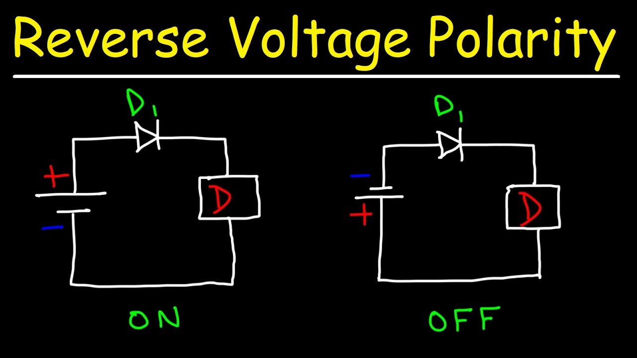
Reverse Polarity Circuit Protection Using Diodes
Показать описание
This electronics video tutorial explains how to protect your circuits from reverse polarity damage using diodes.
Full-Wave Bridge Rectifiers:
Voltage Multiplier Circuit:
Light Emitting Diodes:
Power Dissipation In LEDs & Diodes:
LED Resistor Value:
________________________________
Potentiometers - Variable Resistance:
LED Dimmer Circuit:
Thermistors - Temperature Sensors:
Zener Diodes:
Voltage Regulators - Zener Diodes:
Zener Diode Solar Cell:
________________________________
Power Zener Diodes - Voltage Regulation:
12V LED Battery Level Indicator:
High Voltage Surge Protection Circuit:
AC DC Polarity Tester Circuit:
_______________________________
DC to AC Reverse Polarity Circuit:
Varactor Diodes - Voltage Capacitors:
Final Exams and Video Playlists:
Full-Length Videos and Worksheets:
 0:08:04
Reverse Polarity Circuit Protection Using Diodes
 0:06:46
How to protect circuits from reversed voltage polarity!
 0:11:40
How to Protect Your Devices Against Reverse Polarity Using Ideal Diodes
 0:08:51
What is the best Reverse Voltage Protection Circuit? || Repairing a Lab Bench Power Supply
 0:12:56
Reverse Polarity Protection Explained: Stop Circuit Damage!
 0:09:44
Different types of Reverse Voltage Protection types | What is the need? Reverse polarity Protection
 0:08:21
{543} How to Protect DC Circuit With Reverse Polarity Protection Using N-Channel MOSFET
 0:06:39
5 ways to protect your circuit from reversed polarity
 0:01:27
Protect Your Circuitry from Polarity Reversal with MOSFET !!
 0:03:16
One Parts Circuit - How To Make Reverse Polarity Protection Circuit
 0:02:03
Electronics diy:anti-reverse connection/circuit protection/anti-reverse polarity circuit.
 0:05:45
Reverse Polarity Protection Circuit Using Diodes..Protect Circuits From Reversed Voltage Polarity..
 0:03:27
Reverse Polarity Protection Circuit Using Diodes | Protect Circuits From Reversed Voltage Polarity
 0:07:18
No, THIS is the best reverse polarity protection circuit!
 0:02:11
Reverse Polarity Protection Circuit Using Mosfet
 0:06:42
Classic Circuits You Should Know: Reverse Polarity Protection Circuit Solderstick Wire Connector
 0:04:25
How to make Reverse Polarity Protection Circuit
 0:12:01
Low Cost Reverse Polarity and Over Current Protection (Corrected)
 0:06:00
{540} How to Protect Circuits From Reversed Voltage Polarity / DC Reverse Polarity Protection
 0:05:36
Use Diode for Protection Reverse polarity protection and Stored Energy Protection
 0:13:30
LTSpice Reverse Polarity Protection Using MOSFET | Simulation
 0:06:42
Power tips: Reverse polarity vs. reverse current protection options
 0:02:40
how to protect circuit from reverse voltage polarity
 0:09:27
How to implement Reverse Polarity Protection in your Circuits! ll Diodes & MOSFETS
Комментарии