filmov
tv
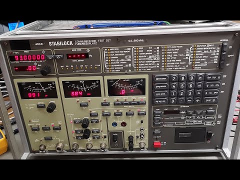
WAVETEK SCHLUMBERGER STABILOCK 4031 Repair and Fix

Показать описание
WAVETEK SCHLUMBERGER STABILOCK 4031 Repair and Fix
Thanks to Paul Kelly G3SDH
for the Repair documents and web information.
Download service manuals.
Do these repairs at your own risk, this video is for information only.
The 4031 RF Attenuator fix can be found on the following link.
This is a comprehensive repair, you will need the service manual, for card and component identification. If the Power supply rails , 5v, 15 and -15v are correct check the rear Card 1 10Mhz output is not drifting, if all OK move onto the removable cards, change all the 10uF, 2.2uF, 22uF, 47uF and 100uF SMD capacitors, around 50-70 caps, take your time and check all the tracks after replacing the capacitors. I would suggest trying a few different removal techniques.
I also checked all the SMD RF coils/chokes on every Panel. Two were found to be open circuit.
UHF SYNTH 213-041
BOARD 461-436 03, REPLACE L3 560nH
FM Modulator 217 031
BOARD 461 455 05, REPLACE L3 10uH.
To do in circuit tests, you will need Riser/extender cards.
Not all the cards have capacitors that need changing but i would recommend a visual inspection for damaged tracks, dry joints etc.
 0:10:26
WAVETEK Schlumberger Stabilock SI 4031 RF Attenuator fault and Fix
 0:17:20
WAVETEK SCHLUMBERGER STABILOCK 4031 Repair and Fix
 0:06:56
Schlumberger Stabilock 4039 (4040) attenuator board repair.
 0:00:45
Anleitung - Selbsttest 4031 Stabilock - MESTEC GmbH
 0:00:24
WAVETEK 4032 STABILOCK POCSAG Melder test
 0:00:36
Stabilock 4031 weird driftin fault affecting the video signal to the VDU
 0:00:29
LCD Röhrenmonitor im Vergleich - 4031 Stabilock - MESTEC GmbH
 1:08:07
Wavetek 3001 RF Signal Generator Checkout and Repair PART 1
 0:01:00
Stabilock SI 4031
 0:00:48
WAVETEK 4032 STABILOCK Funkmessplatz Selbsttest
 0:00:44
Schlumberger Stabilock 4040 Selbsttest Fehler
 0:27:57
Wavetek Model 3001 RF Signal Generator Repair and Calibration Part 2
 0:23:31
schlumberger 4922 radio code analyzer test teardown
 0:52:47
Schlumberger Stabilock 4040 0.4 to 990Mhz repair power supply teardown (part 1)
 0:02:40
Schlumberger Stabilock 4040 System Test
 0:28:54
Pequeña review de monitor de servicio Stabilock SI 4031
 0:01:00
SELBSTTEST STABILOCK
 0:29:34
Schlumberger 4901 RF-AF Measuring Unit, repair and Teardown
 0:01:15
Anleitung - Selbsttest 4015 Stabilock - MESTEC GmbH
 0:00:37
Stabilock 4015 Radio Kielce
 0:44:43
Stabilock 4015 Overview and Mini Teardown
 0:00:29
Stabilock 4040 Test für den Verkauf, hier 2 Fehler
 0:00:23
4031 kHz Channel Marker D
 0:00:17
Heath schlumberger auto range frequency counter
Комментарии