filmov
tv
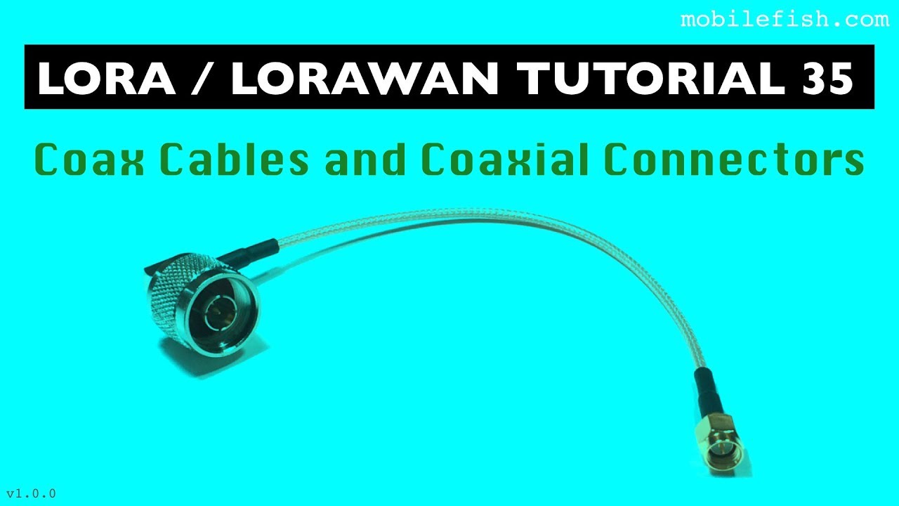
LoRa/LoRaWAN tutorial 35: Coax Cables and Coaxial Connectors
Показать описание
If you like this video and want to support me, go this page for my donation Paypal or crypto addresses:
This is part 35 of the LoRa/LoRaWAN tutorial.
In this video series different topics will be explained which will help you to understand LoRa/LoRaWAN.
It is recommended to watch each video sequentially as I may refer to certain LoRa/LoRaWAN topics explained earlier.
In this tutorial I will explain:
- The different types of coaxial cables and connectors.
- What characteristic impedance is and how it is calculated.
- What the impact is of cable losses.
To transport radio frequency signals, a coaxial cable or coax cable is used.
Coax cables uses the RG ratings and RG stands for Radio Guide.
The number after RG refers to different cable specifications.
For example RG58, RG174, etc.
The higher the RG number, the thinner the central conductor core is.
The suffix U for Universal means for general utility use, for example RG 174/U.
A coax cable (or any type of transmission line) impedance is called characteristic impedance and usually written as Z0 and cannot be measured by an ohmmeter.
A transmission line characteristic impedance is measured by an instrument called the time domain reflectometer or an oscilloscope.
This impedance is a measure of resistance to the flow of electrical energy.
There are two main types of coaxial cables, ones with an impedance of 75 Ω and ones with an impedance of 50 Ω.
In general 50 Ω coax cables are used for data communications (LoRa, WiFi, etc.) or amateur radio.
In general 75 Ω coax cables are used for digital audio or video applications.
The coax cable impedance remains constant regardless of the length of the cable.
A signal travelling thru a coax cable losses power, also known as attenuation.
This signal power loss is measured in decibels per meter (dB/m).
These losses are mainly caused by:
- The conductor, in the form of ohmic losses.
Think of impurities in the conductor.
- The dielectric touching the conductor.
The dielectric absorb some of the energy transported by the conductor.
To avoid signal loss:
Always keep the coax cable as short as possible and preferably connect the antenna directly to the device.
Minimise the number of connectors.
As the gateway should be 50 Ω, always use 50 Ω coax cables otherwise this will result in impedance mismatch thus a bad VSWR.
Coaxial connectors are used to connect coax cables to other devices and maintain the cable’s shielding.
There are two coaxial connectors types: male and female.
A male connector (aka plug) has a metal pin which protrude from the center and a female connector (aka jack) has a recessed hole to receive the pin.
There are several coaxial connector types. In this tutorial only two types will be discussed: type N connectors and SMA connectors.
Type N connectors are threaded connectors and are larger, tougher and can withstand abuse compared to SMA connectors.
Type N connectors are available with 50 Ω and 75 Ω impedance.
When using a thicker coax cable, than type N connector is the best choice.
In general type N connectors are not waterproof.
SMA (SubMiniature version A) connectors are connector interfaces for coaxial cables with screw type coupling mechanism.
The connector has a 50 Ω impedance.
SMA connectors are smaller in size and are used together with smaller size coax cables.
In general SMA connectors are not waterproof.
There are two types of SMA connectors (technically they behave the same):
A standard polarity SMA male or SMA female connector: SMA male / SMA female
A Reverse Polarity SMA male or SMA female connector: RP SMA male / RP SMA female
To determine which is which is a two step process:
1. Barrel with a thread inside: SMA male
Barrel with a thread outside: SMA female
2. If SMA male has a centre sleeve (hole): RP SMA male
If SMA female has a centre pin: RP SMA female
A standard polarity SMA male connector has a center pin surrounded by barrel with inside threads, and the standard SMA female connector has a center sleeve surrounded by a barrel with outside threads.
A reversed-polarity SMA male connector has a center sleeve surrounded by barrel with inside threads, and the reversed-polarity SMA female connector has a center pin surrounded by a barrel with outside threads.
Check out all my other LoRa/LoRaWAN tutorial videos:
Subscribe to my YouTube channel:
The presentation used in this video tutorial can be found at:
#mobilefish #lora #lorawan
 0:10:22
LoRa/LoRaWAN tutorial 35: Coax Cables and Coaxial Connectors
 0:06:19
LoRa/LoRaWAN tutorial 37: Balanced and Unbalanced Feed Lines and Antennas and Balun
 0:06:27
LoRa/LoRaWAN tutorial 24: ABP Demonstration With The Things Network
 0:20:25
#112 LoRa / LoRaWAN De-Mystified / Tutorial
 0:27:45
Workshop: Antenna tuning for your LoRaWAN device - Fabien Ferrero (Université Côte d’Azur)
 0:20:19
LoRa/LoRaWAN tutorial 29: Semtech UDP Packet Forwarder and Semtech UDP protocol
 0:27:43
LoRa/LoRaWAN tutorial 42: Monopole Antenna and Ground Plane
 0:22:47
LoRa/LoRaWAN tutorial 44: Quarter Wave Ground Plane Antenna
 0:25:21
LoRa/LoRaWAN tutorial 48: Yagi-Uda Antenna
 0:19:18
Using 3rd party ModBus sensors with a ModBus to LoRaWAN interface - Franco Zampicinini (Enginko)
![COAXIAL [COAX] CABLES](https://i.ytimg.com/vi/baOOyqRgslA/hqdefault.jpg) 0:06:10
0:06:10
COAXIAL [COAX] CABLES & THEIR COMMON CONNECTORS | COAXIAL CABLE VS TWISTED PAIR CABLE
 1:00:07
Coax Cable and Connectors – The Timorous Art of Terminations
 0:05:20
LoRA - Eine Übertragungsart für APRS
 0:04:31
AM100 Series LoRaWAN® Sensor Configuration Guide
 0:02:46
Connecting Wired Ethernet to the LoRaWAN Gateway Box
 0:00:57
BigCatCables.com Colored RF Coaxial Connectors
 0:07:34
Weatherproof and UV protect your Coax Cable Connector - DX Engineering
 0:50:30
Discover LoRaWAN with Waziup
 0:05:04
Everynet
 0:02:31
Installing an 'F' Type Connector on a Piece of RG6 Coax cable,Coax Cable Installation,Tone...
 1:07:58
LoRa - Long-Range Radio for IoT | Arduino, ESP32, RPI Pico
 0:27:38
How LoRa Modulation really works - long range communication using chirps
 0:15:41
SMA CONNECTOR TUTORIAL
 0:04:48
PL-259 Connectors
Комментарии