filmov
tv
Using a GPS module as variable frequency reference standard

Показать описание
This video shows how to build a variable frequency reference standard using an inexpensive GPS module and a few extra components.
It also shows why some frequencies have a lot of jitter and how to avoid excessive jitter.
U-Center can be downloaded from the Ublox website
It also shows why some frequencies have a lot of jitter and how to avoid excessive jitter.
U-Center can be downloaded from the Ublox website
 0:00:13
DIY GPS tracker using 4G & GPS module 🔥🔥
 0:40:48
Using a GPS module as variable frequency reference standard
 0:00:17
NEO - M8N GPS Module - Arduino
 0:14:03
GPS Module with Arduino- Ublox NEO-6M
 0:05:34
Getting Started with GY-NEO6MV2 NEO-6M GPS Module & Arduino | How to Use & Setup Tutorial
 0:00:08
ESP32 with Neo 6M GPS Module Arduino | GPS Speedometer Arduino | Neo6m Speedometer GPS | ESP32 GPS
 0:50:00
GPS Modules with Arduino and Raspberry Pi
 0:00:38
ARDUINO GPS TRACKER WITH GOOGLE MAPS
 0:09:16
NEO 6M GPS Module with Arduino : Introduction Video
 0:07:31
How to use NEO-6M GPS module with Arduino and get GPS location.
 0:00:16
Variants of GPS 6M module | Tracking with Arduino
 0:16:26
How to use Neo 6M GPS module with Raspberry Pi and Python
 0:30:37
How to use a GPS module with any PIC microcontroller
 0:03:10
How to use neo 6m GPS module with Arduino
 0:00:12
GPS NEO 6M | GPS MODULE | NEO-6M | GPS | #diy #electronics #gps #arduino #location #indore #trending
 0:03:33
GPS Module Tutorial | GPS NEO 6M/7M/8M | Arduino
 0:01:00
Ultimate GPS Teardown - Collin’s Lab Notes #adafruit #collinslabnotes
 0:00:33
Thinnest Wireless GPS Tracker! 🔥
 0:04:34
Getting started with GPS module | NEO-6M | Arduino
 0:06:19
Getting Started with GPS Tracking Device | RY82530 | Tutorial
 0:07:13
How to Connect GPS module with Arduino || HINDI
 0:02:53
SMS Based Vehicle Tracking System with A9G GSM+GPS Module and Arduino
 0:05:07
What is gps module and how it works | GPS NEO 6M/7M/8M | Arduino | UPM Tech
 0:07:46
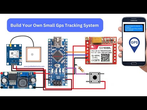
Build Your Own Small Gps Tracking System
Комментарии