filmov
tv
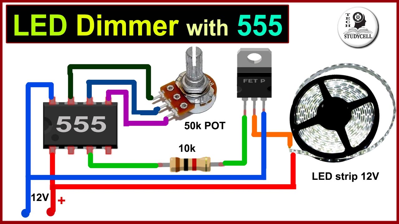
LED strip dimmer circuit using 555 ic | PWM LED dimmer
Показать описание
In this video, we will make a simple 12v LED strip dimmer circuit using a 555 timer. We can easily control led brightness with this 555 PWM LED dimmer circuit.
Required components for the LED strip dimmer circuit
1. 555 timer ic 1no
2. IRFZ44N MOSFET 1no
3. 50k Potentiometer or trimmer 1no
4. 0.1uF ceramic capacitor 2no
5. 1k Resistors 2no
6. 1N4007 Diodes 2no
7. Breadboard
During the video, I have shared both the breadboard schematic and circuit diagram of the PWM led dimmer. Here we can easily control the 12v led brightness with the potentiometer.
#LEDdimmer #555ic #TechStudyCell
Working of the 555 led dimmer circuit:
The 555 timer Astable arrangement creates a square wave with time high and time low. The ratio of these times can be varied by changing R1, R2 and C1 in a typical 555 astable arrangement.
Here we have made R2 (50K POT) as a variable resistor for changing the duty cycle of the output signal. Capacitor C1 Charging through D1 diode and Discharge through D2 diode will generate PWM signal at 555 timer's output pin (PIN3). Accordingly, the MOSFET turns on and off.
The time the square wave is high can be calculated by 0.7 x (R1+R2) x C1
The time the square was is low can be calculated by 0.7 x R2 x C1
This a very useful 555 ic project and after watching this video you can easily make this led dimmer circuit on the breadboard.
If you have enjoyed the video please hit the like button and share it with your friends. For more such videos don't forget to SUBSCRIBE to our channel and please do share your feedback in comment sections. Thank you for your Support.
Other useful videos:
How to make Flashing LED light for Bike using Transistor
How To Test All Electronic Components with Multimeter
How to make a Music Rhythm LED Flash Light
 0:05:38
SUPER simple 1 min DIY 1$ LED strip dimmer ( TWO PARTS ONLY ! )
 0:00:22
How to connect triac dimmable led driver ?
 0:02:51
How To Make 12V Led Dimmer Circuit
 0:04:23
LED strip dimmer circuit using 555 ic | PWM LED dimmer
 0:15:36
LED Dimmer controller design - Electronics engineering pulse width modulation
 0:05:32
Build your own LED Dimmer Driver
 0:04:09
DIY led dimmer simple circuit
 0:02:46
How to make LED Strip Brightness Controller? | LED Strip Dimmer Circuit
 0:00:14
Dimmer switch with different modes #dimmer switch for led strip#dimmer #switch led #Flasher
 0:05:09
LED Strip Dimmer Circuit
 0:06:55
Simple & Easy Dimmer Circuit using 555 IC for LED Strip Lights | DIY
 0:00:46
Use resistor to dim down LEDs - less bright
 0:06:49
LED Strip Dimmer Teardown
 0:04:50
Simple LED Dimmer Circuit
 0:05:08
LED Dimmer Circuit - Brightness Control Using a Potentiometer
 0:06:18
LED Strip Balance and Dimmer Circuit
 0:02:14
How To Make Simple Dimmer Circuit | Led Dimmer Circuit Using One Transistor Only | DIY Led Dimmer
 0:04:15
How to make LED Strip Brightness controller-led strip dimmer
 0:03:56
Make Led strip light brightness controller, diy Led dimmer circuit
 0:05:18
led strip dimmer circuit
 0:05:07
Simple 4 volt LED light controller circuit || LED dimmer circuit
 0:02:08
Led Brightness Controller | Led Strip Brightness Control | led dimmer circuit | @ActiveCreations38
 0:01:46
How to Connect Multiple LED Drivers to A Single Dimmer/Lighting Controller
 0:00:18
Light Box LED Power Supply Transformer 12V 100W 8.5A Aluminium LED Driver Constant Voltage
Комментарии