filmov
tv
Understanding Standing Wave Ratio: SWR & VSWR #SWR #VSWR

Показать описание
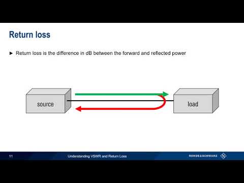
VSWR or voltage standing wave ratio is a phenomenon that occurs on radio frequency feeders.
VSWR, voltage standing wave ratio is an important parameter in many areas, and especially where transmitters are used.
When looking at VSWR it is necessary to look at feeder and load impedances.
It is found that to transfer the maximum amount of power from a feeder to a load, the two must have the same impedance.
Coaxial feeder, twin-line feeder, waveguide and strip-line feeder all have a characteristic impedance. If the load has a different impedance then not all the power can be transferred and the remaining power is reflected back along the feeder.
The voltages and currents from the forward and reverse power combine together and set up standing waves along the feeder. It is found that peaks and troughs occur as a result of the standing waves. These peaks and troughs can rise to twice the voltage of current for a complete mismatch, i.e. infinity to 1 VSWR.
For lesser values of VSWR, the plot of voltage against current along the feeder is less marked.
Accordingly it is possible to defined the voltage standing wave ratio, VSWR as the maximum voltage divided by the minimum voltage.
The reflection coefficient is also a very useful quantity when looking at VSWR. This is the voltage of the forward waveform divided by the voltage of the reflected waveform. It is also possible to obtain the VSWR from a knowledge of the forward and reflected powers. These are all described in the video.
s
 0:06:28
Understanding Standing Wave Ratio: SWR & VSWR #SWR #VSWR
 0:10:10
Understanding VSWR and Return Loss
 0:01:08
What is Standing Wave Ratio (SWR)?
 0:06:15
How to Use an SWR Meter: standing wave ratio meter - guidelines & tips
 0:06:50
SWR (Standing Wave Ratio) Explained
 0:02:50
Inside Wireless: VSWR, |S11|, Return Loss
 0:00:16
Standing Wave Pattern Animation (SWR)
 0:10:14
SWR explained
 0:05:42
Day 16 : CB Radio - What is standing wave ratio (swr)
 0:10:51
#208: Visualizing RF Standing Waves on Transmission Lines
 0:00:35
Standing Wave Ratio SWR test (Video17 )
 0:03:31
What is standing wave ratio (swr)
 0:09:24
Electro Magnetics - Voltage Standing Wave Ratio
 0:02:12
SWR ( Standing Wave Ratio )
 0:13:09
The basics of VSWR and Return Loss
 0:02:31
SWR- Standing Wave Ratio
 0:00:59
What is Standing Wave Ratio (SWR)?
 0:30:24
Lecture 3j -- Standing Waves
 0:30:23
SWR Demystified: AD#28
 0:17:07
LoRa/LoRaWAN tutorial 33: VSWR or SWR and Reflection Coefficient or S11
 0:21:02
SWR Explained And What This Means For Your Ham Radio Station
 0:18:51
CB Radio-The SWR (Standing Wave Ratio) Explained
 0:06:52
What is SWR (in layman's terms)
 0:03:20
Standing wave ratio (SWR) of transmission line | EM - Module - 4 | Lecture 66
Комментарии