filmov
tv
STM32 TIMERS #1. PWM Output || DMA

Показать описание
________________________________________________________________________________________
________________________________________________________________________________________
******* SUPPORT US BY DONATING******
*******Join the Membership*******
________________________________________________________________________________________
******* SUPPORT US BY DONATING******
*******Join the Membership*******
 0:12:36
STM32 TIMERS #1. PWM Output || DMA
 0:20:24
STM32 Guide #3: PWM + Timers
 0:13:42
STM32 TIMERS #9. One Pulse Mode
 0:16:47
Lecture 13: Timer PWM Output
 0:02:22
It takes 2 mins to generate PWM signal in STM32
 0:37:44
Stm32 Timers in PWM mode
 0:12:33
Hands-On with STM32 Timers: Complementary Variable Frequency PWM
 0:10:15
Hands-On with STM32 Timers: Dead-time Insertion in Complementary PWM Output
 0:10:14
Hands-On with STM32 Timers: Custom Signal Generation using PWM and DMA , Part 1 of 2
 0:22:24
STM32 Microcontroller Tutorial 4: Generate PWM Signals with Desired Frequency and Duty Cycle
 0:14:39
Getting Started with STM32 and Nucleo Part 6: Timers and Timer Interrupts | Digi-Key Electronics
 0:07:13
STM32 || Configure Timer || Timer Prescaler, Counter period, Counter mode
 0:18:31
STM32 PWM basics
 0:07:35
STM32 Basic timer explanation
 0:18:38
How to generate a PWM Signal with STM32
 0:04:17
STM32 General Purpose Timer : Understanding Input Capture (IC) Mode -2
 0:15:38
STM32 TIMERS #5. Master Slave Synchronization using the TRIGGER MODE
 0:11:51
Generate PWM Signal in STM32 Microcontroller- Brightness Control of LED
 0:13:57
STM32 TIMERS #4. INPUT CAPTURE || Frequency and Width
 0:08:49
Hands-On with STM32 Timers: Internal Triggering System
 0:00:35
STM32 Timer Complementary PWM Mode using Potentiometer
![[STM32] 1. Using](https://i.ytimg.com/vi/BJ1TSERVI5M/hqdefault.jpg) 0:33:08
0:33:08
[STM32] 1. Using timer & PWM output (STM32F429I-DISC1)
 0:09:01
STM32 TIMERS #6. Timer Synchronization || 3 Phase PWM
 0:10:46
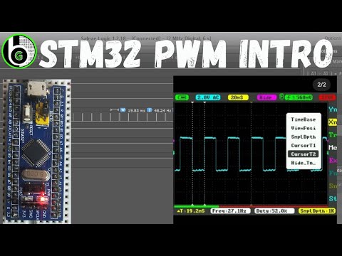
STM32 PWM mode intro|TIMER1||TIMER2||Output Compare Mode|| PWM||Blue Pill||ARR||CNT||CCRx bare metal
Комментарии